CRT1-AD04 / DA02
Analog I/O Slave Units
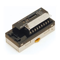
Convert to Smart for Smarter Processing! Simple and Intelligent Analog I/O Slaves
Related Contents
- Features
- Lineup
- Specifications
- Dimensions
- Catalog / Manual / CAD / Software
last update: September 24, 2012
Basic Performance Specifications
| Item | Specification |
|---|---|
| Communications power supply voltage | 14 to 26.4 VDC |
| I/O power supply voltage *1 | 20.4 to 26.4 VDC (24 VDC -15%/+10%) |
| Noise immunity | Conforms to IEC 61000-4-4, 2 kV (power line). |
| Vibration resistance | 10 to 60 Hz with double-amplitude of 0.7 mm, 60 to 150 Hz and 50 m/s2 in X, Y, and Z directions for 80 min each |
| Shock resistance | 150 m/s2 (3 times each in 6 directions on 3 axes) |
| Dielectric strength | 500 VAC (between isolated circuits) |
| Insulation resistance | 20 MΩ min. (between isolated circuits) |
| Ambient operating temperature | -10 to 55°C |
| Ambient operating humidity | 25% to 85% (with no condensation) |
| Ambient operating atmosphere | No corrosive gases |
| Storage temperature | -25 to 65°C |
| Storage humidity | 25% to 85% (with no condensation) |
| Terminal block screw tightening torque *2 | M3 wiring screws: 0.5 Nm M3 mounting screws: 0.5 Nm |
| Installation | Mounted on 35-mm DIN Track or Mounting Bracket, or secured with M4 screws (depending on model) |
*1 The I/O power supply is called the sensor power supply in information for the CRT1-VAD04S.
*2 Applicable only to Slaves to which screw terminal blocks are mounted.
Input Section Specifications
| Item | Specification | ||
|---|---|---|---|
| Voltage input | Current input | ||
| Model | CRT1-AD04 | ||
| Input signal ranges | 0 to 5 V 1 to 5 V 0 to 10 V -10 to 10 V |
0 to 20 mA 4 to 20 mA |
|
| Maximum signal input | ±15 V | ±30 mA | |
| Input impedance | 1 MΩ min. | Approx. 250 Ω | |
| Resolution | 1/6,000 (full scale) | ||
| Overall accuracy | 25°C | ±0.3% FS | ±0.4% FS |
| -10 to 55°C | ±0.6% FS | ±0.8% FS | |
| Conversion cycle | 1 ms/1 points | ||
| AD conversion data | -10 to 10 V range: F448 to 0BB8 hex full scale (-3,000 to 3,000) Other ranges: 0000 to 1770 hex full scale (0 to 6,000) AD conversion range: ±5% FS of the above data ranges. |
||
| Isolation method | Photocoupler isolation (between input and communications lines) No isolation between input signal wires |
||
| Mounting | DIN Track mounting | ||
| Power supply type | Multi-power supply | ||
| Communications power current consumption | 110 mA max. for 24-VDC power supply 175 mA max. for 14-VDC power supply |
||
| Weight | 153 g | ||
Output Section Specifications
| Item | Specification | ||
|---|---|---|---|
| Voltage output | Current output | ||
| Model | CRT1-DA02 | ||
| Output signal ranges | 0 to 5 V 1 to 5 V 0 to 10 V -10 to 10 V |
0 to 20 mA 4 to 20 mA |
|
| External output allowable load resistance | 1 kΩ min. | 600 Ω max. | |
| Resolution | 1/6,000 (full scale) | ||
| Overall accuracy | 25°C | ±0.4% FS | ±0.4% FS * |
| -10 to 55°C | ±0.8% FS | ±0.8% FS * | |
| Conversion cycle | 2 ms/2 points | ||
| DA conversion data | -10 to 10 V range: F448 to 0BB8 hex full scale (-3,000 to 3,000) Other ranges: 0000 to 1770 hex full scale (0 to 6,000) AD conversion range: ±5% FS of the above data ranges. |
||
| Isolation method | Photocoupler isolation (between output and communications lines) No isolation between output signal wires. |
||
| Mounting | DIN Track mounting | ||
| Power supply type | Multi-power supply | ||
| Communications power current consumption | 125 mA max. for 24-VDC power supply 205 mA max. for 14-VDC power supply |
||
| Weight | 155 g | ||
* The specified accuracy does not apply below 0.2 mA when using the 0 to 20 mA range.
last update: September 24, 2012