E5CN-H
Advanced Digital Temperature Controller (48 x 48 mm)
A New High-performance Controller: High Resolution, High Speed, and High Input Accuracy. Logic Operations and Preventive Maintenance Function.
Related Contents
- Features
- Lineup
- Specifications
- Dimensions
- Catalog / Manual / CAD / Software
last update: November 8, 2021
Ratings
| Power supply voltage | No D in model number: 100 to 240 VAC, 50/60 Hz
D in model number: 24 VAC, 50/60 Hz; 24 VDC |
|
|---|---|---|
| Operating voltage range | 85% to 110% of rated supply voltage | |
| Power consumption | 100 to 240 VAC: 8.5 VA (max.) (E5CN-HR2 at 100 VAC: 3.0 VA)
24 VAC/VDC: 5.5 VA (24 VAC)/3.5 W (24 VDC) (max.) (E5CN-HR2D at 24 VAC: 2.7 VA) |
|
| Sensor input | Any of the following can be selected (i.e., fully universal input).
Thermocouple: K, J, T, E, L, U, N, R, S, B, W, or PL II Platinum resistance thermometer: Pt100 or JPt100 Current input: 4 to 20 mA or 0 to 20 mA Voltage input: 1 to 5 V, 0 to 5 V, or 0 to 10 V |
|
| Input impedance | Current input: 150 Ω max., Voltage input: 1 MΩ min. (Use a 1:1 connection when connecting the ES2-HB-N.) | |
| Control method | ON/OFF control or 2-PID control (with auto-tuning) | |
| Control
output |
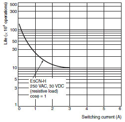
Relay output | SPST-NO, 250 VAC, 3 A (resistive load), electrical life: 100,000 operations, minimum applicable load: 5 V, 10 mA |
| Voltage output
(for driving SSR) |
Output voltage: 12 VDC ±15% (PNP), max. load current: 21 mA, with short-circuit protection circuit | |
| Current output | 4 to 20 mA DC/0 to 20 mA DC, load: 600 Ω max., resolution: approx. 10,000 * | |
| Linear voltage output | 0 to 10 VDC (load: 1 kΩ min.), Resolution: Approx. 10,000 | |
| Auxiliary
output |
Number of outputs | 2 max. |
| Output specifications | Relay output: SPST-NO, 250 VAC, 3 A (resistive load), electrical life: 100,000 operations, minimum applicable load: 5 V, 10 mA | |
| Event
input |
Number of outputs | 2 |
| External contact
input specifications |
Contact input: ON: 1 kΩ max., OFF: 100 kΩ min. | |
| Non-contact input: ON: Residual voltage: 1.5 V max., OFF: Leakage current: 0.1 mA max. | ||
| Current flow: Approx. 7 mA per contact | ||
| Logic
operations |
Number of operations | 8 max. (Combinations can be made using work bits.) |
| Operations | • Logic operation:
Any of the following four patterns can be selected. The input status may be inverted. (A and B) or (C and D), (A or C) and (B or D), A or B or C or D, A and B and C and D (A, B, C, and D are four inputs.) • Delay: ON delay or OFF delay for the results of the logic operation given above. Setting time: 0 to 9999 s or 0 to 9999 min • Output inversion: Possible |
|
| Outputs | One work bit per operation | |
| Work bit
assignments |
Any of the following can be assigned to up to eight work bits (logic operation results): Event input operations, auxiliary outputs, or control outputs. | |
| Transfer
outputs |
Number of outputs | 1 max. |
| Output
specifications |
Current output: 4 to 20 mA DC, Load: 600 Ω max., Resolution at 4 to 20 mA: Approx. 10,000 | |
| RSP input | Not supported | |
| Setting method | Digital setting using front panel keys | |
| Indication method | 11-segment digital display and individual indicators (7-segments displays also possible)
Character height: PV: 11 mm, SV: 6.5 mm |
|
| Bank switching | Supported (number of banks: 8)
Local SP, alarm settings, PID sets (PID constants, MV upper limit, MV lower limit, etc.) |
|
| Other functions | Manual output, heating/cooling control, loop burnout alarm, SP ramp, other alarm functions, heater burnout detection, 40% AT, 100% AT, MV limiter, input digital filter, self-tuning, temperature input shift, run/stop, protection functions, control output ON/OFF counter, extraction of square root, MV change rate limit, PV/SV status display, logic operations, automatic cooling coefficient adjustment | |
| Ambient operating temperature | -10 to 55°C (with no condensation or icing), for 3-year warranty: -10 to 50°C | |
| Ambient operating humidity | 25% to 85% | |
| Storage temperature | -25 to 65°C (with no condensation or icing) | |
* For models with current outputs, control output 1 can be used as a transfer output.
Input Ranges
Thermocouple/Platinum Resistance Thermometer/Analog Input (Fully Universal Inputs)
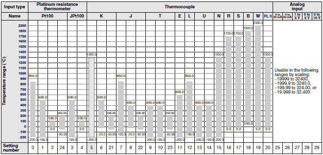
Shaded settings are the default settings.
The applicable standards for the input types are as follows:
K, J, T, E, N, R, S, B: JIS C 1602-1995, IEC 584-1
L: Fe-CuNi, DIN 43710-1985
U: Cu-CuNi, DIN 43710-1985
W: W5Re/W26Re, ASTM E988-1990
JPt100: JIS C 1604-1989, JIS C 1606-1989
Pt100: JIS C 1604-1997, IEC 751
PL II: According to Platinel II electromotive force charts from BASF (previously Engelhard)
Alarm Outputs
Each alarm can be independently set to one of the following 13 alarm types. The default is 2: Upper limit.
Auxiliary outputs are allocated for alarms. ON delays and OFF delays (0 to 999 s) can also be specified.
Auxiliary outputs are allocated for alarms. ON delays and OFF delays (0 to 999 s) can also be specified.
Note: For models with heater burnout, SSR failure, and heater overcurrent detection, alarm 1 will be an OR output of the
alarm selected from the following alarm types and the alarms for heater burnout, SSR failure, and heater
overcurrent. To output only a heater burnout alarm, SSR failure alarm, and heater overcurrent alarm for alarm 1,
set the alarm type to 0 (i.e., no alarm function).
alarm selected from the following alarm types and the alarms for heater burnout, SSR failure, and heater
overcurrent. To output only a heater burnout alarm, SSR failure alarm, and heater overcurrent alarm for alarm 1,
set the alarm type to 0 (i.e., no alarm function).
| Set
value |
Alarm type | Alarm output operation | Description of function | |
|---|---|---|---|---|
| When alarm value
X is positive |
When alarm value
X is negative |
|||
| 0 | Alarm function OFF | Output OFF | No alarm | |
| 1 *1 | Upper- and lower-limit |
 |
*2 | Set the deviation in the set point by setting the alarm upper
limit (H) and alarm lower limit (L). |
| 2 | Upper-limit |
 |
 |
Set the upward deviation in the set point by setting the alarm
value (X). |
| 3 | Lower-limit |
 |
 |
Set the downward deviation in the set point by setting the
alarm value (X). |
| 4 *1 | Upper- and lower-limit range |
 |
*3 | Set the deviation in the set point by setting the alarm upper
limit (H) and alarm lower limit (L). |
| 5 *1 | Upper- and lower-limit with
standby sequence |
 *5 *5 |
*4 | A standby sequence is added to the upper- and lower-limit
alarm (1). *6 |
| 6 | Upper-limit with standby
sequence |
 |
 |
A standby sequence is added to the upper-limit alarm (2). *6 |
| 7 | Lower-limit with standby
sequence |
 |
 |
A standby sequence is added to the lower-limit alarm (3). *6 |
| 8 | Absolute-value upper-limit |
 |
 |
The alarm will turn ON if the process value is larger than the
alarm value (X) regardless of the set point. |
| 9 | Absolute-value lower-limit |
 |
 |
The alarm will turn ON if the process value is smaller than the
alarm value (X) regardless of the set point. |
| 10 | Absolute-value upper-limit
with standby sequence |
 |
 |
A standby sequence is added to the absolute-value upper-limit
alarm (8). *6 |
| 11 | Absolute-value lower-limit
with standby sequence |
 |
 |
A standby sequence is added to the absolute-value lower-limit
alarm (9). *6 |
| 12 | LBA (alarm 1 type only) | --- | *7 | |
| 13 | PV change rate alarm | --- | *8 | |
*1. With set values 1, 4 and 5, the upper and lower limit values can be set independently for each alarm type, and are
expressed as “L” and “H.”
*2. Set value: 1, Upper- and lower-limit alarm

*3. Set value: 4, Upper- and lower-limit range

*4. Set value: 5, Upper- and lower-limit with standby sequence
For Upper- and Lower-Limit Alarm Described Above
• Case 1 and 2
Always OFF when the upper-limit and lower-limit hysteresis overlaps.
• Case 3: Always OFF
*5. Set value: 5, Upper- and lower-limit with standby sequence Always OFF when the upper-limit and lower-limit
hysteresis overlaps.
*6. Refer to the E5CN/E5AN/E5EN/E5GN Digital Temperature Controllers User's Manual Basic Type (Cat. No. H156) for
information on the operation of the standby sequence.
*7. Refer to the E5CN/E5AN/E5EN/E5GN Digital Temperature Controllers User's Manual Basic Type (Cat. No. H156) for
information on the loop burnout alarm (LBA).
*8. Refer to the E5CN/E5AN/E5EN/E5GN Digital Temperature Controllers User's Manual Basic Type (Cat. No. H156) for
information on the PV change rate alarm.
expressed as “L” and “H.”
*2. Set value: 1, Upper- and lower-limit alarm
*3. Set value: 4, Upper- and lower-limit range
*4. Set value: 5, Upper- and lower-limit with standby sequence
For Upper- and Lower-Limit Alarm Described Above
• Case 1 and 2
Always OFF when the upper-limit and lower-limit hysteresis overlaps.
• Case 3: Always OFF
*5. Set value: 5, Upper- and lower-limit with standby sequence Always OFF when the upper-limit and lower-limit
hysteresis overlaps.
*6. Refer to the E5CN/E5AN/E5EN/E5GN Digital Temperature Controllers User's Manual Basic Type (Cat. No. H156) for
information on the operation of the standby sequence.
*7. Refer to the E5CN/E5AN/E5EN/E5GN Digital Temperature Controllers User's Manual Basic Type (Cat. No. H156) for
information on the loop burnout alarm (LBA).
*8. Refer to the E5CN/E5AN/E5EN/E5GN Digital Temperature Controllers User's Manual Basic Type (Cat. No. H156) for
information on the PV change rate alarm.
Characteristics
| Indication accuracy | Thermocouple: (± 0.1% of indicated value or ± 1 °C, whichever is greater) ± 1 digit max. *1
Platinum resistance thermometer: (± 0.1% of indicated value or ± 0.5 °C, whichever is greater) ± 1 digit max. Analog input: ± 0.1% FS ± 1 digit max. CT input: ± 5% FS ± 1 digit max. |
|
|---|---|---|
| Transfer output accuracy | ± 0.3% FS max. | |
| Influence of temperature
*2 |
Thermocouple input (R, S, B, W, PLII): (± 1% of PV or ± 10 °C, whichever is greater) ± 1 digit max.
Other thermocouple input: (± 1% of PV or ± 4 °C, whichever is greater) ± 1 digit max. *3 Platinum resistance thermometer: (± 1% of PV or ± 2 °C, whichever is greater) ± 1 digit max. Analog input: (± 1%FS) ± 1 digit max. |
|
| Influence of voltage *2 | ||
| Influence of EMS.
(at EN 61326-1) |
||
| Input sampling period | 60 ms | |
| Hysteresis | Temperature input: 0.1 to 3240.0 °C or ° F (in units of 0.1 °C or ° F)
Analog input: 0.01% to 99.99% FS (in units of 0.01% FS) |
|
| Proportional band (P) | Temperature input: 0.1 to 3240.0 °C or ° F (in units of 0.1 °C or ° F)
Analog input: 0.1% to 999.9% FS (in units of 0.1% FS) |
|
| Integral time (I) | 0.0 to 3240.0 s (in units of 0.1 s) | |
| Derivative time (D) | 0.0 to 3240.0 s (in units of 0.1 s) | |
| Control period | 0.5, 1 to 99 s (in units of 1 s) | |
| Manual reset value | 0.0 to 100.0% (in units of 0.1%) | |
| Alarm setting range | -19999 to 32400 (decimal point position depends on input type) | |
| Affect of signal source
resistance |
Thermocouple: 0.1°C/Ω max. (100 Ω max.)
Platinum resistance thermometer: 0.1°C/Ω max. (10 Ω max.) |
|
| Insulation resistance | 20 MΩ min. (at 500 VDC) | |
| Dielectric strength | 2,300 VAC, 50 or 60 Hz for 1 min (between terminals with different charge) | |
| Vibration
resistance |
Malfunction | 10 to 55 Hz, 20 m/s2 for 10 min each in X, Y, and Z directions |
| Destruction | 10 to 55 Hz, 0.75-mm single amplitude for 2 hrs each in X, Y, and Z directions | |
| Shock
resistance |
Malfunction | 100 m/s2, 3 times each in X, Y, and Z directions |
| Destruction | 300 m/s2, 3 times each in X, Y, and Z directions | |
| Weight | Controller: Approx. 150 g, Mounting Bracket: Approx. 10 g | |
| Degree of protection | Front panel: IP66, Rear case: IP20, Terminals: IP00 | |
| Memory protection | Non-volatile memory (number of writes: 1,000,000 times) | |
| Setup Tool | CX-Thermo version 4.0 or higher | |
| Setup Tool port | Provided on the bottom of the E5CN-H. Use this port to connect a computer to the E5CN-H.
An E58-CIFQ1 USB-Serial Conversion Cable is required to connect the computer to the E5CN-H. *4 |
|
| Standards | Approved
standards |
UL 61010-1, CSA C22.2 No. 1010-1 |
| Conformed
standards |
EN 61010-1 (IEC 61010-1): Pollution level 2, overcurrent category II, Lloyd's standards *5 | |
| EMC | EMI: EN 61326-1 *6
Radiated Interference Electromagnetic Field Strength: EN 55011 Group 1, class A Noise Terminal Voltage: EN 55011 Group 1, class A EMS: EN 61326-1 *6 ESD Immunity: EN 61000-4-2 Electromagnetic Field Immunity: EN 61000-4-3 Burst Noise Immunity: EN 61000-4-4 Conducted Disturbance Immunity: EN 61000-4-6 Surge Immunity: EN 61000-4-5 Power Frequency Magnetic Field Immunity: EN 61000-4-8 Voltage Dip/Interrupting Immunity: EN 61000-4-11 |
|
*1. The indication accuracy of K thermocouples in the -200 to 1300°C range, T and N thermocouples at a temperature of
-100°C max., and U and L thermocouples at any temperatures is ±2°C ±1 digit max. The indication accuracy of the
B thermocouple at a temperature of 400°C max. is not specified. The indication accuracy of B thermocouples in the
400 to 800°C range is ±3°C max. The indication accuracy of the R and S thermocouples at a temperature of 200°C
max. is ±3°C ±1 digit max. The indication accuracy of W thermocouples is ±0.3 of PV or ±3°C, whichever is greater,
±1 digit max. The indication accuracy of PL II thermocouples is ±0.3 of PV or ±2°C, whichever is greater, ±1 digit
max.
*2. Ambient temperature: -10°C to 23°C to 55°C, Voltage range: −15% to 10% of rated voltage
*3. K thermocouple at -100°C max.: ±10°C max.
*4. External communications (RS-232C or RS-485) and cable communications for the Setup Tool can be used at the
same time.
*5. Refer to information on maritime standards in Safety Precautions for E5[]N/E5[]N-H for compliance with Lloyd's
Standards.
*6. Industrial electromagnetic environment (EN/IEC 61326-1 Table 2)
USB-Serial Conversion Cable
| Applicable OS | Windows XP/Vista/7/8/8.1/10 |
|---|---|
| Applicable software | CX-Thermo version 4 or higher |
| Applicable models | E5AN/E5EN/E5CN/E5CN-U/E5AN-H/E5EN-H/E5CN-H |
| USB interface standard | Conforms to USB Specification 1.1. |
| DTE speed | 38400 bps |
| Connector specifications | Computer: USB (type A plug)
Temperature Controller: Setup Tool port (on bottom of Controller) |
| Power supply | Bus power (Supplied from USB host controller.) |
| Power supply voltage | 5 VDC |
| Current consumption | 70 mA |
| Ambient operating temperature | 0 to 55°C (with no condensation or icing) |
| Ambient operating humidity | 10% to 80% |
| Storage temperature | - 20 to 60°C (with no condensation or icing) |
| Storage humidity | 10% to 80% |
| Altitude | 2,000 m max. |
| Weight | Approx. 100 g |
Note: A driver must be installed in the personal computer. Refer to installation information in the operation manual for
the Conversion Cable.
the Conversion Cable.
Communications Specifications
| Transmission line
connection method |
RS-485: Multipoint
RS-232C: Point-to-point |
|---|---|
| Communications | RS-485 (two-wire, half duplex)/RS-232C |
| Synchronization method | Start-stop synchronization |
| Protocol | CompoWay/F, SYSWAY, or Modbus |
| Baud rate | 1200, 2400, 4800, 9600, 19200, 38400, or 57600 bps |
| Transmission code | ASCII (CompoWay/F, SYSWAY)
RTU (Modbus) |
| Data bit length * | 7 or 8 bits |
| Stop bit length * | 1 or 2 bits |
| Error detection | Vertical parity (none, even, odd)
Frame check sequence (FCS) with SYSWAY Block check character (BCC) with CompoWay/F or CRC-16 Modbus |
| Flow control | None |
| Interface | RS-485, RS-232C |
| Retry function | None |
| Communications buffer | 217 bytes |
| Communications
response wait time |
0 to 99 ms
Default: 20 ms |
* The baud rate, data bit length, stop bit length, and vertical parity can be individually set using the Communications
Setting Level.
Current Transformer (Order Separately) Ratings
| Dielectric strength | 1,000 VAC for 1 min |
|---|---|
| Vibration resistance | 50 Hz, 98 m/s2 |
| Weight | E54-CT1: Approx. 11.5 g, E54-CT3: Approx. 50 g |
| Accessories (E54-CT3 only) | Armatures (2) Plugs (2) |
Heater Burnout Alarms, SSR Failure Alarms, and Heater Overcurrent Alarms
| CT input (for heater current detection) | Models with detection for single-phase heaters: One input
Models with detection for single-phase or three-phase heaters: Two inputs |
|---|---|
| Maximum heater current | 50 A AC |
| Input current indication accuracy | ±5% FS ±1 digit max. |
| Heater burnout alarm setting range *1 | 0.1 to 49.9 A (in units of 0.1 A)
Minimum detection ON time: 100 ms |
| SSR failure alarm setting range *2 | 0.1 to 49.9 A (in units of 0.1 A)
Minimum detection OFF time: 100 ms |
| Heater overcurrent alarm setting range *3 | 0.1 to 49.9 A (in units of 0.1 A)
Minimum detection ON time: 100 ms |
*1. For heater burnout alarms, the heater current will be measured when the control output is ON, and the output
assigned to the alarm 1 function will turn ON if the heater current is lower than the set value (i.e., heater burnout
detection current value).
*2. For SSR failure alarms, the heater current will be measured when the control output is OFF, and the output assigned
to the alarm 1 function will turn ON if the heater current is higher than the set value (i.e., SSR failure detection
current value).
*3. For heater overcurrent alarms, the heater current will be measured when the control output is ON, and the output
assigned to the alarm 1 function will turn ON if the heater current is higher than the set value (i.e., heater
overcurrent detection current value).
Electrical Life Expectancy Curve for Relays (Reference Values)
last update: November 8, 2021