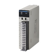
CS1W-MAD44
SYSMAC CS-series Analog I/O Unit
For Various Analog I/Os
Related Contents
- Features
- Lineup
- Specifications
- Dimensions
- Catalog / Manual / CAD / Software
last update: October 9, 2013
| Item | CS1W-MAD44 | ||||
|---|---|---|---|---|---|
| Applicable PLC model | CS series | ||||
| Unit type | CS1 Special I/O Unit | ||||
| Isolation | Between I/O and PLC signals: Photocoupler (No isolation between individual I/O signals.) | ||||
| External terminals | 21-point detachable terminal block (M3 screws) | ||||
| Power consumption | 200 mA max. at 5 VDC, 200 mA max. at 26 VDC | ||||
| Dimensions (mm) *1 | 35 × 130 × 126 (W × H × D) | ||||
| Weight | 450 g max. | ||||
| General specifications | Conforms to general specifications for SYSMAC CS-series Series. | ||||
| Mounting position | CS-series CPU Rack or CS-series Expansion Rack
(Cannot be mounted to a C200H Expansion I/O Rack or a SYSMAC BUS Slave Rack.) |
||||
| Maximum number of
Units |
Units per Rack
(CPU Rack or Expansion Rack) *2 |
Power Supply Unit | Maximum number of Units per Rack | ||
| C200HW-PA204
C200HW-PA204S C200HW-PA204R C200HW-PD024 |
3 Units max. | ||||
| C200HW-PA209R | 6 Units max. | ||||
| Units per basic
system |
When C200HW-PA209R Power Supply Units only are used:
6 Units max. × 8 Racks = 48 Units max. |
||||
| Data exchange with
CPU Units |
Special I/O Unit Area
CIO 200000 to CIO 295915 (Words CIO 2000 to CIO 2959) |
Exchanges 10
words of data per Unit. |
CPU Unit to
Analog I/O Unit |
Analog output
Peak value hold Conversion Enable Bit |
|
| Analog I/O Unit
to CPU Unit |
Analog input
Input disconnection detection Alarm flags |
||||
| Internal Special I/O
Unit DM Area (D20000 to D29599) |
Transmits 100
words of data per Unit at power-up or when the Unit is restarted. |
CPU Unit to
Analog I/O Unit |
Input signal conversion enable/disable,
input signal range setting Output signal conversion enable/disable, output signal range setting Ratio conversion function setting, constants Output status for output hold Mean value function setting |
||
| Input | Specifications | Input signal *4 | Voltage input | Current input | |
| Number of analog inputs | 4 | ||||
| Input signal range *3 | 1 to 5 V
0 to 5 V 0 to 10 V - 10 to 10 V |
4 to 20 mA | |||
| Maximum rated input (for 1 point) *5 | ± 15 V | ± 30 mA | |||
| Input impedance | 1 M Ω min. | 250 Ω (rated value) | |||
| Resolution | 4,000 (full scale) | ||||
| Converted output data | 16-bit binary data | ||||
| Accuracy *6 | 23 ± 2 °C | ± 0.2% of full scale | ± 0.4% of full scale | ||
| 0 °C to 55 °C | ± 0.4% of full scale | ± 0.6% of full scale | |||
| A/D conversion time *7 | 1.0 ms/point max. | ||||
| Functions | Mean value processing | Stores the last "n" data conversions in the buffer, and stores
the the mean value of the conversion values. Buffer number: n = 2, 4, 8, 16, 32, 64 |
|||
| Peak value holding | Stores the maximum conversion value while the Peak Value
Hold Bit is ON. |
||||
| Input disconnection detection *9 | Detects the disconnection and turns ON the Disconnection
Detection Flag. |
||||
| Output | Specifications | Output signal | Voltage output | ||
| Number of analog outputs | 4 | ||||
| Output signal range *3 | 1 to 5 V
0 to 5 V 0 to 10 V - 10 to 10 V |
||||
| Output impedance (for 1 point) | 0.5 Ω max. | ||||
| Max. output current | 12 mA | ||||
| Resolution | 4,000 (full scale) | ||||
| Set data | 16-bit binary data | ||||
| Accuracy *6 | 23 ± 2 °C | ± 0.3% of full scale | |||
| 0 °C to 55 °C | ± 0.5% of full scale | ||||
| D/A conversion time *7 | 1.0 ms/point max. | ||||
| Functions | Output hold function | Outputs the specified output status (CLR, HOLD, or MAX) under
any of the following circumstances. When the Conversion Enable Bit is OFF. *8 In adjustment mode, when a value other than the output number is output during adjustment. When there is an output setting error or a fatal error occurs at the PLC. When the CPU Unit is on standby. When the Load is OFF. |
|||
| Other | Functions | Ratio conversion function | Stores the results of positive and negative gradient analog
inputs calculated for ratio and bias as analog output values. Positive gradient: Analog output = A × Analog input + B (A = 0 to 99.99, B = 8,000 to 7FFF Hex) Negative gradient: Analog output = F - A × Analog input + B (A = 0 to 99.99, B = 8,000 to 7FFF Hex, F = output range max. value) |
||
*1. Refer to Dimensions for details on the Unit's dimensions.
*2. The maximum number of Analog I/O Units that can be mounted to one Rack will varies depending on the current
consumption of the other Units mounted to the Rack.
*3. Input and output signal ranges can be set for each input and output.
*4. Voltage input or current input are chosen by using the voltage/current switch at the back of the terminal block.
*5. The Analog I/O Unit must be operated according to the input specifications provided here. Operating the Unit outside
these specifications will cause the Unit to malfunction.
*6. The accuracy is given for full scale. For example, an accuracy of ±0.2% means a maximum error of ±8 (BCD).
The default setting is adjusted for voltage input. To use current input, perform the offset and gain adjustments as
required.
*7. A/D conversion time is the time it takes for an analog signal to be stored in memory as converted data after it has
been input. It takes at least one cycle before the converted data is read by the CPU Unit. D/A conversion time is the
time required for converting and outputting the PLC data. It takes at least one cycle for the data stored in the PLC to
be read by the Analog I/O Unit.
*8. When the operation mode for the CPU Unit is changed from RUN mode or MONITOR mode to PROGRAM mode, or
when the power is turned ON, the Output Conversion Enable Bit will turn OFF. The output status specified according
to the output hold function will be output.
*9. Input disconnection detection is valid only when the 1 to 5-V or 4 to 20-mA range is set. If there is no input signal for
when the 1 to 5-V or 4 to 20-mA range is set, the Disconnection Detection Flag will turn ON.
last update: October 9, 2013