Discontinued On Mar. 2024
ZEN V2
Programmable Relay
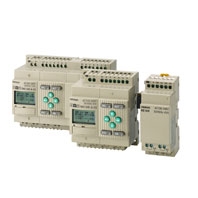
Even Broader Applications with Increased Functionality and Higher Precision
* Information in this page is a reference that you created on the basis of information in the product catalog before the end of production, may be different from the current situation, such as goods for / supported standards options / price / features of the product. Before using, please check the compatibility and safety system.
Related Contents
- Features
- Lineup
- Specifications
- Dimensions
- Catalog / Manual / CAD / Software
last update: August 3, 2016
Ratings
| Item | Specification | |
|---|---|---|
| ZEN-[]C[]AR-A-V2/ZEN-8E1AR | ZEN-[]C[]D[]-D-V2/ZEN-8E1D[] | |
| Rated supply voltage | 100 to 240 VAC, 50/60 Hz | 12 to 24 VDC (DC ripple rate: 5% max.) |
|
Operating voltage range |
85 to 264 VAC | 10.8 to 28.8 VDC |
|
Power consumption |
CPU Units without Expansion I/O Units ZEN-10C1AR-A-V2/ZEN-10C2AR-A-V2/ ZEN-10C3AR-A-V2 100 V AC: 5 VA max. 240 V AC: 7 VA max. ZEN-10C4AR-A-V2 100 V AC: 6 VA max. 240 V AC: 8 VA max. ZEN-20C[]AR-A-V2 100 V AC: 7 VA max. 240 V AC: 10 VA max. CPU Units with three Expansion I/O Units ZEN-10C1AR-A-V2/ZEN-10C2AR-A-V2 100 V AC: 6 VA max. 240 V AC: 8 VA max. ZEN-10C4AR-A-V2 100 V AC: 7 VA max. 240 V AC: 9 VA max. ZEN-20C[]AR-A-V2 100 V AC: 8 VA max. 240 V AC: 11 VA max. Expansion I/O Units ZEN-8E1AR 100 V AC: 3 VA max. 240 V AC: 4 VA max. |
CPU Units without Expansion I/O Units ZEN-10C[]DR-D-V2 12/24 V DC: 3 W max. (ZEN-10C3DR-D-V2: 2.8 W max.) ZEN-10C[]DT-D-V2 12/24 V DC: 2 W max. ZEN-20C[]DR-D-V2 12/24 V DC: 4 W max. ZEN-20C[]DT-D-V2 12/24 V DC: 2 W max. CPU Units with three Expansion I/O Units ZEN-10C[]DR-D-V2 12/24 V DC: 4 W max. ZEN-10C[]DT-D-V2 12/24 V DC: 3 W max. ZEN-20C[]DR-D-V2 12/24 V DC: 5 W max. ZEN-20C[]DT-D-V2 12/24 V DC: 3 W max. Expansion I/O Units ZEN-8E1DR 12/24 V DC: 2 W max. |
| Inrush current | ZEN-10C[]AR-A-V2: 4.5 A max. ZEN-20C[]AR-A-V2: 4.5 A max. ZEN-8E1AR: 4 A max. |
ZEN-10C[]D[]-D-V2: 30 A max. ZEN-20C[]D[]-D-V2: 30 A max. ZEN-8E1DR: 15 A max. |
| Ambient temperature | 0 to 55°C (-25 to 55°C for ZEN-[]C2[][]-[]-V2 models) | |
|
Ambient storage temperature |
-20 to 75°C (-40 to 75°C for ZEN-[]C2[][]-[]-V2 models) | |
| Ambient humidity | 10% to 90% (with no condensation) | |
| Ambient conditions | No corrosive gases | |
| Mounting method | Surface mounting, DIN track mounting (standard (vertical) installation and horizontal installation) (See notes 1 and 2.) |
|
| Terminal block | Solid-line terminal block (use solid wire or fine-stranded wire) | |
|
Terminal screw tightening torque |
0.565 to 0.6 Nm (5 to 5.3 in-lb) | |
| Degree of protection | IP20 (Mounted inside a control panel) | |

Characteristics
| Item | Specification |
|---|---|
| Control method | Stored program control |
| I/O control method | Cyclic scan |
| Programming language | Ladder diagram |
| Program capacity | 96 lines (3 input conditions and 1 output per line) |
| Max. No. of control I/O
points |
44 points *1
CPU Units with 20 I/O points: 12 inputs and 8 outputs Expansion I/O Units: 4 inputs and 4 outputs each, up to 3 Units. |
| LCD display *2 | 12 characters × 4 lines, with backlight |
| Operation buttons *2 | 8 (4 cursor buttons and 4 operation buttons) |
| User program backup | Internal EEPROM, Memory Cassette (optional) |
| Power interruption
hold |
Internal holding bit status, holding timer/counter present values, calendar and clock (year,
month, day of month, day of week, time) • Super capacitor backup time:2 days min. (25°C) • Life of optional battery: 10 years min. (25°C) |
| Calendar and clock
function *2 |
Accuracy: ±15 s/month (at 25°C) |
| Timer accuracy | 0.01 s unit: -0.05% -10 ms max. (rate for set value)
min/s unit: -0.05% -1 s max. (rate for set value) h/min unit: -0.05% -1 min max. (rate for set value) |
| Maximum counting
speed |
150 Hz: 8-Digit counter (F) set to high-speed operations (CPU Units with DC power supplies
only) (The counting speed may be less than 150 Hz depending on the cycle time of the program. See Data Sheet.) |
| Insulation resistance | 20 MΩ (at 500 VDC) min.:
Between power supply terminals and all output terminals. Between terminals of different output circuits. Between all terminals of CPU Unit and all terminals of Expansion I/O Unit. |
| Insulation | Reinforced insulation
Between power supply or input terminals and output terminals. Between terminals of different output circuits. Between all terminals of CPU Unit and all terminals of Expansion I/O Unit. No separation Between power supply and input terminals of the same unit. Between power supply terminals of CPU Unit and computer connector, Battery Unit connector, or all Expansion Unit connectors (all interfaces are live parts). |
| Dielectric strength | 2,300 VAC, 50/60 Hz for 1 min (leakage current 1 mA max.):
Between power supply terminals and all output terminals. Between terminals of different output circuit. Between all terminals of CPU Unit and all terminals of Expansion I/O Unit. |
| Vibration resistance | Conforms to IEC60068-2-6, 5 to 9 Hz with 3.5-mm single amplitude, 9 to 150 Hz
acceleration 9.8 m/s2, 10 sweeps each in X, Y, and Z directions (1 octave/min) |
| Shock resistance | Conforms to IEC60068-2-27, 147 m/s2, 3 times each in X, Y, and Z directions. |
| Weight | CPU Unit with 10 I/O points: Approx. 300 g max.
CPU Unit with 20 I/O points: Approx. 350 g max. Expansion I/O Unit: Approx. 120 g max. |
*1. Up to 34 points for CPU Units with 10 I/O points. With Communications-type CPU Units, however, the CPU Unit has 6
inputs and 3 outputs, for a maximum of 33 I/O points.
*2. Not provided for LED-type CPU Unit without display (i.e., ZEN-[]C2[][]-[]-V2 models).
inputs and 3 outputs, for a maximum of 33 I/O points.
*2. Not provided for LED-type CPU Unit without display (i.e., ZEN-[]C2[][]-[]-V2 models).
Communications Specifications (Communications-type CPU Units)
| Item | ZEN-10C4[]R-[]-V2 |
|---|---|
| Communications | RS-485 (two-wire, half duplex) |
| Synchronization method | Start-stop synchronization |
| Baud rate | 4800, 9600, or 19200 bps |
| Transmission code | ASCII |
| Data bit length | 7 or 8 bits |
| Stop bit length | 1 or 2 bits |
| Error detection | Vertical parity (none, even, odd), Block check character (BCC) |
| Flow control | None |
| Interface | RS-485 |
| Retry function | None |
| Node number | 0 to 99 (default: 1), XX (broadcasting) |
Approved Standards
| Item | Specifications |
|---|---|
| Safety standards | cULus: UL508/CSA C22.2 No.142 (ZEN-PA03024 take Class I Div2)
Conforms to EN/IEC 61131-2 clause 11, excluding 11.7.2.2 (Overvoltage category 2 and Pollution degree II conforms to IEC 60664-1) |
| EMC
(See note.) |
Radiation Field Emission CISPR11 Class A, Group 1
Noise Terminal Voltage Emission CISPR11 Class A, Group 1 |
| Electrostatic Discharge Immunity IEC61000-4-2 In air: 8 kV, In contact: 6 kV
Electromagnetic Field Immunity IEC61000-4-3 10 V/m Electrical Fast Transient/Burst Immunity IEC61000-4-4 Power line AC I/O: 2 kV DC I/O: 1 kV Surge Immunity IEC61000-4-5 Normal Noise AC power supply, AC I/O: 1 kV DC power supply, DC I/O: 0.5 kV Common Noise AC power supply, AC I/O: 2 kV DC power supply: 1 kV DC I/O: 0.5 kV Immunity to Conducted Disturbances Induced by Radio-frequency Fields IEC61000-4-6 3 V Momentary Power Interruption Immunity IEC61131-2 CPU Units with AC Power Supplies: 10 ms max. CPU Units with DC Power Supplies: 2 ms max. (level: PS1) |
Note: EMC conforms to EN 61131-2 clause 8 except in the following cases.
• When Expansion I/O Units with DC inputs are connected to a CPU Unit with an AC power supply, the burst immunity between power supplies will be 1 kv.
• When the signal wire for transistor outputs exceeds 10 m, the surge immunity of DC output signal lines will not conform.
Input Specifications
CPU Units
AC Inputs (Not Isolated)
| Item | Specifications | Circuit drawing |
|---|---|---|
| Input voltage | 100 to 240 VAC +10%, -15%, 50/60 Hz |
 |
| Input impedance | 680 kΩ | |
| Input current | 0.15 mA/100 VAC, 0.35 mA/240 VAC | |
| ON voltage | 80 VAC min. | |
| OFF voltage | 25 VAC max | |
| ON response time | 50 ms or 70 ms at 100 VAC (See note.)
100 ms or 120 ms at 240 VAC (See note.) |
|
| OFF response time |
Note: Can be selected using the filter settings.
DC Inputs: I0 to I3 for Units with 10 I/O points, I0 to I9 for Units with 20 I/O Points (Not Isolated)
| Item | Specifications | Circuit drawing |
|---|---|---|
| Input voltage | 12 to 24 VDC +20%, -10% |
 |
| Input impedance | 5.3 kΩ | |
| Input current | 4.5 mA (typ.)/24 VDC | |
| ON voltage | 8 VDC min. | |
| OFF voltage | 5 VDC max. | |
| ON response time | 15 ms or 50 ms (See note.) | |
| OFF response time |
Note: Can be selected using the input filter settings, except when I0 is being used for an 8-digit counter with a high-
speed input.
speed input.
DC Inputs: I4 and I5 for Units with 10 I/O points, Ia and Ib for Units with 20 I/O Points (Not Isolated)
| Item | Specifications | Circuit drawing | |
|---|---|---|---|
| DC Inputs | Input voltage | 12 to 24 VDC +20%, -10% |  |
| Input impedance | PNP: 5.5 kΩ/14 VDC min.
100 kΩ/14 VDC max. NPN: 5.2 kΩ |
||
| Input current | PNP: 4.3 mA (typ.)/24 VDC
NPN: 4.6 mA (typ.)/24 VDC |
||
| ON voltage | 8 VDC min. | ||
| OFF voltage | 3 VDC max. | ||
| ON response time | 15 ms or 50 ms (See note.) | ||
| OFF response time | |||
| Analog
Inputs |
Input range | 0 to 10 V | |
| External input impedance | 100 kΩ min. | ||
| Resolution | 0.1 V (1/100 FS) | ||
| Accuracy | ±1.5% FS (at ambient operating temperature within rated range) | ||
| AD conversion data | 0 to 10.5 V (in increments of 0.1 V) | ||
Note: Can be selected using the input filter settings.
Expansion I/O Units
AC Inputs (Not Isolated)
| Item | Specifications | Circuit drawing |
|---|---|---|
| Input voltage | 100 to 240 VAC +10%, -15%, 50/60 Hz |
 |
| Input impedance | 680 kΩ | |
| Input current | 0.15 mA/100 VAC, 0.35 mA/240 VAC | |
| ON voltage | 80 VAC min. | |
| OFF voltage | 25 VAC max. | |
| ON response time | 50 ms or 70 ms at 100 VAC (See note.)
100 ms or 120 ms at 240 VAC (See note.) |
|
| Off response time |
Note: Can be selected using the input filter settings.
DC Inputs (ZEN-8E1DR: Not Isolated, ZEN-8E1DT: Photocoupler Isolated)
| Item | Specifications | Circuit drawing |
|---|---|---|
| Input voltage | 12 to 24 VDC +20%, -10% |
 |
| Input impedance | 6.5 kΩ | |
| Input current | 3.7 mA (typ.)/24 VDC | |
| ON voltage | 8 VDC min. | |
| OFF voltage | 5 VDC max. | |
| ON response time | 15 ms or 50 ms (See note 1.) | |
| OFF response time |
Note: 1. Can be selected using the input filter settings.
2. The ZEN-8E1DT has no +/- terminals. There is no need to supply power.
2. The ZEN-8E1DT has no +/- terminals. There is no need to supply power.
Output Specifications (CPU Units and Expansion I/O Units)
Units with Relay Outputs
| Item | Specifications | Circuit drawing | |
|---|---|---|---|
| Maximum switching capacity | 250 VAC/8 A (resistive load: cosΦ = 1)
24 VDC/5 A (resistive load) Use the following values for the total of all outputs. CPU Units with 10 I/O points: 20 A max. (15 A max. for Communications-type CPU Units) CPU Units with 20 I/O points: 40 A max. Expansion I/O Units: 20 A max. |
 |
|
| Minimum switching capacity | 5 VDC/10 mA (resistive load) | ||
| Relay life | Electrical | Resistive load: 50,000 times (cosΦ = 1)
Inductive load: 50,000 times (cosΦ = 0.4) |
|
| Mechanical | 10 million times | ||
| ON response time | 15 ms max. | ||
| OFF response time | 5 ms max. | ||
The life under the worst conditions, of the output contacts used in ZEN relay outputs is given in the above table.
Note: The switching capacity, switching durability, and applicable load area when actually using the relay depend on the
type of load, environmental conditions, and switching conditions.
Therefore, be sure to confirm these conditions for the actual machine before use.
Note: The switching capacity, switching durability, and applicable load area when actually using the relay depend on the
type of load, environmental conditions, and switching conditions.
Therefore, be sure to confirm these conditions for the actual machine before use.
Units with Transistor Outputs
| Item | Specifications | Circuit drawing |
|---|---|---|
| Maximum switching capacity | 24 VDC +20%, 500 mA | |
| Leakage current | 0.1 mA max. | Each circuit is configured with an independent common circuit
 |
| Residual voltage | 1.5 V max. | |
| ON response time | 1 ms max. | |
| OFF response time | 1 ms max. |
last update: August 3, 2016
 Product Category
- Control Components
-
Programmable Relays
-
Discontinued
- ZEN V2
-
Discontinued
-