Discontinued On Mar. 2025
H8PS
Cam Positioner
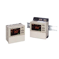
This Compact Cam Positioner, Popular for Its Ease-of-use, Now Comes with Even Better Functions.
* Information in this page is a reference that you created on the basis of information in the product catalog before the end of production, may be different from the current situation, such as goods for / supported standards options / price / features of the product. Before using, please check the compatibility and safety system.
Related Contents
- Features
- Lineup
- Specifications
- Dimensions
- Catalog / Manual / CAD / Software
last update: September 24, 2012
Ratings
| Item | H8PS-[]B | H8PS-[]BF | H8PS-[]BP | H8PS-[]BFP | ||
|---|---|---|---|---|---|---|
| Rated supply voltage | 24 VDC | |||||
| Operating voltage range | 85% to 110% of rated supply voltage | |||||
| Mounting method | Flush mounting | Surface mounting,
track mounting |
Flush mounting | Surface mounting,
track mounting |
||
| Power consumption | Approx. 4.5 W at 26.4 VDC for 8-output models
Approx. 6.0 W at 26.4 VDC for 16-/32-output models |
|||||
| Inputs | Encoder input | Connections to a dedicated absolute encoder | ||||
| External
inputs |
Input signals | 8-output Models: None
16-/32-output Models: Bank inputs 1/2/4, origin input, start input |
||||
| Input type | No voltage inputs: ON impedance:1 kΩ max. (Leakage current: approx. 2 mA at 0 Ω)
ON residual voltage: 2 V max., OFF impedance: 100 kΩ min., Applied voltage: 30 VDC max. Minimum input signal width: 20 ms |
|||||
| Outputs | Cam outputs
RUN output |
NPN open-collector transistor outputs
30 VDC max., 100 mA max. (Do not exceed 1.6 A total for all cam outputs and the RUN output.), residual voltage: 2 VDC max. |
PNP open-collector transistor outputs
30 VDC max. (26.4 VDC for 16-/32- output Models), 100 mA max. (Do not exceed 1.6 A total for all cam outputs and the RUN output.), residual voltage: 2 VDC max. |
|||
| Pulse output | NPN open-collector transistor output
30 VDC max., 30 mA max., residual voltage: 0.5 VDC max. |
PNP open-collector transistor output
30 VDC max. (26.4 VDC for 16-/32- output Models) 30 mA max., residual voltage: 2 VDC max. |
||||
| Number of outputs | 8-output Models: 8 cam outputs, 1 RUN output, 1 pulse output
16-output Models: 16 cam outputs, 1 RUN output, 1 pulse output 32-output Models: 32 cam outputs, 1 RUN output, 1 pulse output |
|||||
| Number of banks | 8 banks (for 16-/32-output Models only) | |||||
| Display method | 7-segment, negative transmissive LCD (Main Display: 11 mm (red), Sub-display:
5.5 mm (green)) |
|||||
| Memory backup method | EEPROM (overwrites: 100000 times min.) that can store data for 10 years min. | |||||
| Ambient operating temperature | -10 to 55°C (with no icing or condensation) | |||||
| Storage temperature | -25 to 65°C (with no icing or condensation) | |||||
| Ambient humidity | 25% to 85% | |||||
| Degree of protection | Panel surface: IP40, Rear case: IP20 | |||||
| Case color | Light gray (Munsell 5Y7/1) | |||||
Characteristics
| Setting unit | 0.5° increments at a resolution of 720, 1° increments at a resolution of 256 or 360 *1 | |
|---|---|---|
| Number of steps | Up to 10 steps can be set for each cam to turn the output ON/OFF 10 times. *2 | |
| Inputs | Encoder input | Connections to a dedicated absolute encoder
Response rotation speed (in Run/Test Mode) 1600 r/min max. at a resolution of 256 or 360 (1200 r/min max. if ADV function is set for 4 or more cams) *3 *4 800 r/min max. at a resolution of 720 (600 r/min max. if ADV function is set for 4 or more cams) Includes error data detection |
| Encoder cable extension
distance |
256/360 resolution
100 m max. at 330 r/min or less 52 m max. at 331 to 1200 r/min (331 to 900 r/min if ADV function is set for 4 or more cams) 12 m max. at 1201 to 1600 r/min (901 to 1200 r/min if ADV function is set for 4 or more cams) 720 resolution 100 m max. at 330 r/min or less 52 m max. at 331 to 600 r/min (331 to 450 r/min if ADV function is set for 4 or more cams) 12 m max. at 601 to 800 r/min (451 to 600 r/min if ADV function is set for 4 or more cams) |
|
| Output response time | 0.3 ms max. | |
| Insulation resistance | 100 MΩ min. (at 500 VDC) between current-carrying terminals and exposed non-
current-carrying metal parts, between all current-carrying parts and the USB connector |
|
| Dielectric strength | 1000 VAC, 50/60 Hz for 1 min between current-carrying terminals and exposed non-
current-carrying metal parts 500 VAC, 50/60 Hz for 1 min between current-carrying section and USB connector, and between current-carrying terminals and non-current-carrying metal part of output connector |
|
| Impulse withstand voltage | 1 kV between power terminals
1.5 kV between current-carrying terminals and exposed non-current-carrying metal parts |
|
| Noise immunity | ±480 V between power terminals, ±600 V between input terminals
Square-wave noise by noise simulator (pulse width: 100 ns/1 μs, 1-ns rise) |
|
| Static immunity | 8 kV (malfunction), 15 kV (destruction) | |
| Vibration
resistance |
Destruction | 10 to 55 Hz with 0.75-mm single amplitude each in 3 directions for 2 hours each |
| Malfunction | 10 to 55 Hz with 0.5-mm single amplitude each in 3 directions for 10 minutes each | |
| Shock
resistance |
Destruction | 300 m/s2 3 times each in 6 directions |
| Malfunction | 200 m/s2 3 times each in 6 directions | |
| Approved safety standards | cULus (Listing): UL508/CSA C22.2 No. 14 | |
| EMC | (EMI) EN61326
Emission Enclosure: EN55011 Group1 Class A (EMS) EN61326 Immunity ESD: EN61000-4-2: 4 kV contact discharge, 8 kV air discharge Immunity RF-interference: EN61000-4-3: 10 V/m (Amplitude-modulated, 80 MHz to 1 GHz), 10 V/m (Pulse-modulated, 900 MHz ±5 MHz) Immunity Conducted Disturbance EN61000-4-6: 10 V (0.15 to 80 MHz) Immunity Burst: EN61000-4-4: 2 kV for power-line, 1 kV for I/O signal-line Immunity Surge: EN61000-4-5: 1 kV line to line (power line), 2 kV line to ground (power line) |
|
| Weight | Approx. 300 g (Cam Positioner main unit only) | |
*1. Cam output precision, however, is 2° max. for Encoder with 256 resolution (P/R).
*2. Although 32-output Models can have 10 steps set for any one output, there must be no more than 160 steps total set
for all cam outputs.
*3. The maximum is 1000 r/min when an E6CP-AG5C-C Encoder is connected.
*4. ADV stands for Advance Angle Compensation.
*2. Although 32-output Models can have 10 steps set for any one output, there must be no more than 160 steps total set
for all cam outputs.
*3. The maximum is 1000 r/min when an E6CP-AG5C-C Encoder is connected.
*4. ADV stands for Advance Angle Compensation.
Functions
| Item | H8PS-8[] | H8PS-16[] | H8PS-32[] |
|---|---|---|---|
| Encoder rotation
direction switching |
Encoder data can be set with a DIP switch to forward (CW) or reverse (CCW) direction. | ||
| Encoder origin
designation |
The present display angular
position can be set to 0° (origin) by pressing the ORIGIN Key on the front panel. |
The present display angular position can be set to 0° (origin)
by using the origin input terminal or the ORIGIN Key on the front panel. Note: All banks use the same origin. |
|
| Angle display switch | Converts the Absolute Encoder value display from 256 divisions/revolution to 360°/
revolution. |
||
| Rotation display monitor | Graphically displays the Encoder rotational angular position. | ||
| Teaching function | Sets the cam output ON/OFF angle based on actual machine (Encoder) operation. | ||
| Pulse output | Outputs a preset number of pulses per Encoder rotation. It also sets the pulse output start
angle. |
||
| Switching the angle and
speed displays |
Displays both the present angular position and the number of Encoder revolutions (speed) in
Run Mode. Switches back and forth between the main display showing the present angular position with the sub-display showing the speed and the main display showing the speed with the sub-display showing the present angular position. |
||
| Bank function | --- | Enables the entire cam program to be changed at one time by
switching banks (0 to 7). The bank that is running can be switched using the bank input terminal or the BANK Key on the front panel. Also enables programs to be copied between banks. |
|
| Advance angle
compensation (ADV) function |
Automatically advances the ON/OFF angle of cam outputs in proportion to machine
(encoder) speed to compensate for the delay in timing of ON/OFF operation. ADV values can be set individually for 7 cam outputs. |
||
| Speed alarm output | A specified cam output can be used as an Encoder speed alarm output.
The function can output upper and lower limit speed alarms. |
||
| All protection function | Disables all key and switch operations in Run Mode to prevent incorrect or unauthorized
operation. |
||
| Cam protection function | Prohibits program changes at the cam output level. Any cam numbers can be protected. | ||
| Step number limit | Limits the number of steps that can be set per cam output. Prohibits incorrect operations
by adding to the program. |
||
| Output prohibit | --- | The start input can be turned OFF in Run or Test Mode to
prohibit cam output. Note: Use this function carefully for the application because no cam outputs are provided when the start input is turned OFF. |
|
| Support Software
settings |
--- | Programs can be uploaded or downloaded easily by connecting a
personal computer to the Cam Positioner using a USB Cable (Recommended USB Cables: ELECOM CO.Ltd. U2C-MF20BK) and the Support Software (H8PS-SOFT-V1, sold separately). |
|
last update: September 24, 2012
 Product Category
- Control Components
-
Cam Positioners
-
Discontinued
- H8PS
-
Discontinued
-