Discontinued On Mar. 2019
ZW Series
Confocal Fiber Displacement Sensor
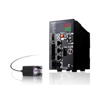
Ultra-compact and Ultra-lightweight. Stable Measurements for Any Material. Robust Sensor Head Structure.
* Information in this page is a reference that you created on the basis of information in the product catalog before the end of production, may be different from the current situation, such as goods for / supported standards options / price / features of the product. Before using, please check the compatibility and safety system.
Related Contents
- Features
- Lineup
- Specifications
- Dimensions
- Catalog / Manual / CAD / Software
last update: May 10, 2017
Sensor Head
| Item | ZW-S07 | ZW-S20 | ZW-S30 | ZW-S40 | ZW-SR07 | ZW-SR20 | ZW-SR40 | |
|---|---|---|---|---|---|---|---|---|
| Measuring center
distance |
7 mm | 20 mm | 30 mm | 40 mm | 7 mm | 20 mm | 40 mm | |
| Measuring range | ±0.3 mm | ±1 mm | ±3 mm | ±6 mm | ±0.3 mm | ±1 mm | ±6 mm | |
| Static resolution *1 | 0.25 μm | 0.25 μm | 0.25 μm | 0.25 μm | 0.25 μm | 0.25 μm | 0.25 μm | |
| Linearity *2 | ±0.8 μm | ±1.2 μm | ±4.5 μm | ±7.0 μm | ±1.1 μm | ±1.6 μm | ±9.3 μm | |
| Spot diameter
*3 |
Near | 20 μm dia. | 45 μm dia. | 70 μm dia. | 90 μm dia. | 20 μm dia. | 45 μm dia. | 90 μm dia. |
| Center | 18 μm dia. | 40 μm dia. | 60 μm dia. | 80 μm dia | 18 μm dia. | 40 μm dia. | 80 μm dia | |
| Far | 20 μm dia. | 45 μm dia. | 70 μm dia. | 90 μm dia | 20 μm dia. | 45 μm dia. | 90 μm dia | |
| Measuring cycle | 500 μs to 10 ms | |||||||
| Applicable sensor
controller |
ZW-C1[][][]/-CE1[][] | |||||||
| Operating ambient
illumination |
Illumination on object surface 10,000 lx or less: incandescent light | |||||||
| Ambient temperature
range |
Operating: 0 to 50°C, Storage: -15 to 60°C
(with no icing or condensation) |
|||||||
| Ambient humidity range | Operating and storage: 35% to 85% (with no condensation) | |||||||
| Degree of protection | IP40 (IEC60529) | |||||||
| Vibration resistance
(destructive) |
10 to 150 Hz, 0.35 mm single amplitude, 80 min each in X, Y, and Z directions | |||||||
| Shock resistance
(destructive) |
150 m/s2 3 times each in six directions (up/down, left/right, forward/backward) | |||||||
| Temperature
characteristic *4 |
0.6 μm/ °C | 1.5 μm/ °C | 2.8 μm/ °C | 4.8 μm/ °C | 0.6 μm/ °C | 1.5 μm/ °C | 4.8 μm/ °C | |
| Materials | Case: aluminum die-cast
Fiber cable sheat: PVC Calibration ROM: PC |
|||||||
| Fiber cable length | 0.3 m, 2 m (Flex-resistant cable) | |||||||
| Fiber cable minimum
bending radius |
20 mm | |||||||
| Insulation resistance
(Calibration ROM) |
Between case and all terminals: 20 MΩ (by 250 V megger) | |||||||
| Dielectric strength
(Calibration ROM) |
Between case and all terminals: 1,000 VAC, 50/60 Hz, 1 min | |||||||
| Weight | Approx. 105 g (Chassis, fiber cable total) | |||||||
| Accessories included
with sensor head |
Fixing screw (M2) for Calibration ROM, Strap × 1, Instruction sheet, Precautions for correct use | |||||||
*1. Capacity value when Omron standard mirror surface target is measured at the measurement center distance as the
average of 4,096 times.
*2. Material setting for the Omron standard mirror surface target: Error from an ideal straight line when measuring on
mirror surface.
The reference values for linearity when targets to measure other than the above are as in the table below.
| Item | ZW-S07 | ZW-S20 | ZW-S30 | ZW-S40 | ZW-SR07 | ZW-SR20 | ZW-SR40 |
|---|---|---|---|---|---|---|---|
| Glass | ±1.0 μm | ±1.2 μm | ±4.5 μm | ±7.0 μm | ±1.1 μm | ±1.6 μm | ±9.3 μm |
| SUS BA | ±1.2 μm | ±1.4 μm | ±5.5 μm | ±8.5 μm | ±1.2 μm | ±1.8 μm | ±9.3 μm |
| White ceramic | ±1.6 μm | ±1.7 μm | ±6.4 μm | ±9.5 μm | ±1.6 μm | ±1.9 μm | ±11.0 μm |
*3. Capacity value defined by 1/e2 (13.5%) of the center optical intensity in the measured area.
*4. Temperature characteristic at the measurement center distance when the Sensor Head and the target are the fastened
with an aluminum jig and the Sensor Head and the Controller are set in the same temperature environment.
Automation Software Sysmac Studio
System Requirements
| Item | Requirement |
|---|---|
| Operating system (OS)
*1 *2 |
Windows XP (Service Pack 3 or higher, 32-bit version)/Windows Vista (32-bit version)/
Windows 7 (32-bit/64-bit version)/Windows 8 (32-bit/64-bit version)/Windows 8.1 (32-bit/ 64-bit version)/Windows 10 (32-bit/64-bit version) |
| CPU | Windows computers with Celeron 540 (1.8 GHz) or faster CPU.
Core i5 M520 (2.4 GHz) or equivalent or faster recommended |
| Main memory | 2 GB min. |
| Recommended
videomemory/video card for using 3D motion trace |
Video memory: 512 MB min.
Video card: Either of the following video cards: • NVIDIAR GeForceR 200 Series or higher • ATI RadeonHD5000 Series or higher |
| Hard disk | At least 1.6 GB of available space |
| Display | XGA 1024 × 768, 16 million colors.
WXGA 1280 × 800 min. recommended |
| Disk drive | DVD-ROM drive |
| Communications ports | USB port corresponded to USB 2.0, or Ethernet port *3 |
| Supported languages | Japanese, English, German, French, Italian, Spanish, simplified Chinese, traditional Chinese,
Korean |
*1. Sysmac Studio Operating System Precaution: System requirements and hard disk space may vary with the system
environment.
*2. The following restrictions apply when Sysmac Studio is used with Microsoft Windows Vista or Windows 7.
Some Help files cannot be accessed.
The Help files can be accessed if the Help program distributed by Microsoft for Windows (WinHlp32.exe) is installed.
Refer to the Microsoft homepage listed below or contact Microsoft for details on installing the file. (The download
page is automatically displayed if the Help files are opened while the user is connected to the Internet.)
http://support.microsoft.com/kb/917607/en-us
*3. Refer to the hardware manual for your Controller for hardware connection methods and cables to connect the
computer and Controller.
Setting Software Smart Monitor ZW ZW-SW101
System Requirements
| Item | Condition |
|---|---|
| Operating System(OS) | Windows 7 (32 or 64-bit version)
Windows XP (Service Pack3 or more, 32-bit version) |
| CPU | Intel Pentium III, 850 MHz or more (2 GHz or more is recommended.) |
| Main memory | 1 GB or more |
| Hard disk | 50 MB or more |
| Display | 1024 × 768 dots or more, 16 million colors or more |
| Supported languages | Japanese/English |
| Communication port | Ethernet port |
Controller
| Item | ZW-CE10T | ZW-CE15T | |||
|---|---|---|---|---|---|
| Input/Output type | NPN | PNP | |||
| Number of connected Sensor Heads | 1 per Controller | ||||
| Applicable sensor head | ZW-S[][]/-SR[][] | ||||
| Light source for measurement | White LED | ||||
| Segment
display |
Main display | 11-segment red display, 6 digits | |||
| Sub-display | 11-segment green display, 6 digits | ||||
| LED
display |
Status indicators | HIGH (orange), PASS (green), LOW (orange), STABILITY (green),
ZERO (green), ENABLE (green), THRESHOLD-H (orange), HRESHOLD-L (orange), RUN (green) |
|||
| EtherCAT indicators | L/A IN (Link Activity IN) (green), L/O OUT (Link Activity OUT)
(green), ECAT RUN (green), ECAT ERR (red) |
||||
| External
inter- face |
Ethernet | 100BASE-TX, 10BASE-T, No-protocol Communications (TCP/
UDP), EtherNet/IPTM |
|||
| EtherCAT | EtherCAT-specific protocol 100BASE-TX | ||||
| RS-232C | 115,200 bps max. | ||||
| Analog
output terminal block |
Analog voltage output
(OUT1V) |
-10 V to +10 V, output impedance: 100 Ω | |||
| Analog current output
(OUT1A) |
4 mA to 20 mA, maximum load resistance: 300Ω | ||||
| 32-pole
exten- sion con- nector |
Judgment output
(HIGH1/PASS1/LOW1) |
Transistor output system
Output voltage: 21.6 to 30 VDC Load current: 50 mA or less Residual voltage when turning ON: 1.2 V or less Leakage voltage when turning OFF: 0.1 mA or les |
|||
| BUSY output (BUSY1) | |||||
| ALARM output (ALARM1) | |||||
| ENABLE output (ENABLE) | |||||
| LED OFF input (LED OFF1) | DC input system
Input voltage: 24 VDC ⋅10% (21.6 to 26.4 VDC) Input current: 7 mA Typ. (24 VDC) Voltage/Current when turning ON: 19 V/3 mA or more Voltage/Current when turning OFF:5 V/1 mA or less |
||||
| ZERO RESET input (ZERO) | |||||
| TIMING output (TIMING1) | |||||
| RESET output (RESET1) | |||||
| Bank | Selected bank output
(BANK_OUT 1 to 3) |
Transistor output system
Output voltage: 21.6 to 30 VDC Load current: 50 mA or less Residual voltage when turning ON: 1.2 V or less Leakage voltage when turning OFF: 0.1 mA or less |
|||
| Selected bank input
(BANK_SEL 1 to 3) |
DC input system
Input voltage: 21.6 to 26 VDC Input current: 7 mA Typ. (24 VDC) Voltage/Current when turning ON: 19 V/3 mA or more Voltage/Current when turning OFF:5 V/1 mA or less |
||||
| Main
func- tions |
Exposure time | Auto/Manual | |||
| Measuring cycle | 500 μs to 10 ms | ||||
| Material setting | Standard/Mirror/Diffusion surfaces | ||||
| Measurement Item | Height/Thickness/Calculation | ||||
| Filtering | Median/Average/Differentiation/High pass/Low pass/Band pass | ||||
| Outputs | Scaling/Different holds/Zero reset/Logging for a measured
value |
||||
| Display | Measured value/Threshold value/Analog output voltage or
current value/Judgment result/Resolution/Exposure time |
||||
| Number of configurable banks | Max. 8 banks | ||||
| Task process | Multi-task (up to 4 tasks per bank) | ||||
| System | Save/Initialization/Display measurement information/
Communication settings/Sensor Head calibration/Key-lock/ Trigger-key input |
||||
| Ratings | Power supply voltage | 21.6 to 26.4 VDC (including ripple) | |||
| Current consumption | 600 mA max. | ||||
| Insulation resistance | Across all lead wires and controller case: 20 MΩ (by 250 V
megger) |
||||
| Dialectic strength | Across all lead wires and controller case: 1,000 VAC, 50/60 Hz,
1 min. |
||||
| Environ-
mental |
Degree of protection | IP20 (IEC60529) | |||
| Vibration resistance (destructive) | 10 to 55 Hz, 0.35-mm single amplitude, 50 min each in X, Y, and
Z directions |
||||
| Shock resistance (destructive) | 150 m/s2, 3 times each in six directions (up/down, left/right,
forward/backward) |
||||
| Ambient temperature | Operating: 0 to 40°C
Storage: -15 to 60°C (with no icing or condensation) |
||||
| Ambient humidity | Operating and storage: 35% to 85% (with no condensation) | ||||
| Grounding | D-type grounding (Grounding resistance of 100 Ω or less)
Note: For conventional Class D grounding |
||||
| Materials | Case: PC | ||||
| Weight | Approx. 750 g (main unit only), Approx. 150 g (Parallel Cable) | ||||
| Accessories included with controller | Instruction sheet, Member registration sheet,
Parallel cable ZW-XCP2E |
||||
Note: Controllers with binary outputs are also available (ZW-C10T/-C15T). Please contact your OMRON sales
representative for details.
ZW Series EtherCAT Communications Specifications
| Item | Specification |
|---|---|
| Communications standard | IEC61158 Type12 |
| Physical layer | 100BASE-TX (IEEE802.3) |
| Connectors | RJ45 × 2
ECAT IN: EtherCAT input ECAT OUT: EtherCAT output |
| Communications media | Category 5 or higher (cable with double, aluminum tape and braided shielding) is
recommended. |
| Communications distance | Distance between nodes: 100 m max. |
| Process data | Variable PDO mapping |
| Mailbox (CoE) | Emergency messages, SDO requests, SDO responses, and SDO information |
| Distributed clock | Synchronization in DC mode. |
| LED display | L/A IN (Link/Activity IN) × 1, AL/A OUT (Link/Activity OUT) × 1, AECAT RUN × 1,
AECAT ERR × 1 |
last update: May 10, 2017
 Product Category
- Sensors
-
Displacement Sensors / Measurement Sensors
-
Discontinued
- ZW Series
-
Discontinued
-