J7MN
Motor Protection Circuit Breaker (MPCB)
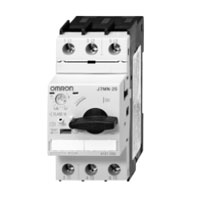
MPCB system (motor protection CLASS 10)
Related Contents
- Features
- Lineup
- Specifications
- Dimensions
- Catalog / Manual / CAD / Software
last update: February 3, 2014
Components for Fuseless Load Feeders, DIN-Rail Mounting
Type of coordination „1“ 3 x 415 V 10 kA (other conditions on request)
| Motor 3~400V
kW |
Setting range
A |
Circuit-breaker
Type |
Contactor
220-230V 50Hz Type |
Link module
Type |
DIN-rail adapter
Type |
|---|---|---|---|---|---|
| - | 0.11 - 0.16 | J7MN-25-E16 | J7KN-10-10 230 | J74MN-VD-12 | J74MN-HU |
| - | 0.14 - 0.2 | J7MN-25-E2 | J7KN-10-10 230 | J74MN-VD-12 | J74MN-HU |
| 0.06 | 0.18 - 0.25 | J7MN-25-E25 | J7KN-10-10 230 | J74MN-VD-12 | J74MN-HU |
| 0.09 | 0.22 - 0.32 | J7MN-25-E32 | J7KN-10-10 230 | J74MN-VD-12 | J74MN-HU |
| - | 0.28 - 0.4 | J7MN-25-E4 | J7KN-10-10 230 | J74MN-VD-12 | J74MN-HU |
| 0.12 | 0.35 - 0.5 | J7MN-25-E5 | J7KN-10-10 230 | J74MN-VD-12 | J74MN-HU |
| 0.18 | 0.45 - 0.63 | J7MN-25-E63 | J7KN-10-10 230 | J74MN-VD-12 | J74MN-HU |
| - | 0.55 - 0.8 | J7MN-25-E8 | J7KN-10-10 230 | J74MN-VD-12 | J74MN-HU |
| 0.25 | 0.7 - 1 | J7MN-25-1 | J7KN-10-10 230 | J74MN-VD-12 | J74MN-HU |
| 0.37 | 0.9 - 1.25 | J7MN-25-1E25 | J7KN-10-10 230 | J74MN-VD-12 | J74MN-HU |
| 0.55 | 1.1 - 1.6 | J7MN-25-1E6 | J7KN-10-10 230 | J74MN-VD-12 | J74MN-HU |
| 0.75 | 1.4 - 2 | J7MN-25-2 | J7KN-10-10 230 | J74MN-VD-12 | J74MN-HU |
| - | 1.8 - 2.5 | J7MN-25-2E5 | J7KN-10-10 230 | J74MN-VD-12 | J74MN-HU |
| 1.1 | 2.2 - 3.2 | J7MN-25-3E2 | J7KN-10-10 230 | J74MN-VD-12 | J74MN-HU |
| 1.5 | 2.8 - 4 | J7MN-25-4 | J7KN-10-10 230 | J74MN-VD-12 | J74MN-HU |
| - | 3.5 - 5 | J7MN-25-5 | J7KN-10-10 230 | J74MN-VD-12 | J74MN-HU |
| 2.2 | 4.5 - 6.3 | J7MN-25-6E3 | J7KN-10-10 230 | J74MN-VD-12 | J74MN-HU |
| 3 | 5.5 - 8 | J7MN-25-8 | J7KN-10-10 230 | J74MN-VD-12 | J74MN-HU |
| 4 | 7 - 10 | J7MN-25-10 | J7KN-10-10 230 | J74MN-VD-12 | J74MN-HU |
| 5.5 | 9 - 12.5 | J7MN-25-12E5 | J7KN-14-10 230 | J74MN-VD-12 | J74MN-HU |
| 7.5 | 11 - 16 | J7MN-25-16 | J7KN-18-10 230 | J74MN-VD-12 | J74MN-HU |
| - | 14 - 20 | J7MN-25-20 | J7KN-22-10 230 | J74MN-VD-25 | J74MN-HU |
| - | 17 - 22 | J7MN-25-22 | J7KN-22-10 230 | J74MN-VD-25 | J74MN-HU |
| 11 | 20 - 25 | J7MN-25-25 | J7KN-22-10 230 | J74MN-VD-25 | J74MN-HU |
Technical Data according to IEC/EN 60947-1, 60947-2, 60947-4-1 and VDE 0660
This table shows the rated ultimate short-circuit breaking capacity Icu and the rated service short-circuit breaking capacity Ics of the J7MN circuit-breakers with different operational voltages as a function of the rated current In of the circuit-breakers.
The circuit-breakers can be fed at the top or bottom supply terminals without any reduction of the rated data.
If the short-circuit current exceeds the rated short-circuit breaking capacity of the circuit-breaker specified in the tables at the installation point, a back-up fuse is to be used.
The maximum rated current for the back-up fuse is specified in the tables. These fuses are only suitable for the short-circuit-currents as indicated on the fuses.
| Circuit-
breaker Type |
Rated
current In A |
up to AC 240V *1 | up to AC 400V *1
up to AC 415V *2 |
up to AC 440V *1
up to AC 460V *2 |
||||||
|---|---|---|---|---|---|---|---|---|---|---|
| Icu
kA |
Ics
kA |
max.
fuse (gL/gG) A |
Icu
kA |
Ics
kA |
max.
fuse (gL/gG) A |
Icu
kA |
Ics
kA |
max.
fuse (gL/gG) A |
||
| J7MN-12 | 0.16 to 0.8 | 100 | 100 | -- | 100 | 100 | -- | 100 | 100 | -- |
| 1 | 100 | 100 | -- | 100 | 100 | -- | 100 | 100 | -- | |
| 1.25 | 100 | 100 | -- | 100 | 100 | -- | 100 | 100 | -- | |
| 1.6 | 100 | 100 | -- | 100 | 100 | -- | 100 | 100 | -- | |
| 2 | 100 | 100 | -- | 100 | 100 | -- | 100 | 100 | -- | |
| 2.5 | 100 | 100 | -- | 100 | 100 | -- | 100 | 100 | -- | |
| 3.2 | 100 | 100 | -- | 100 | 100 | -- | 10 | 10 | 40 | |
| 4 | 100 | 100 | -- | 100 | 100 | -- | 10 | 10 | 40 | |
| 5 | 100 | 100 | -- | 100 | 100 | -- | 10 | 10 | 50 | |
| 6.3 | 100 | 100 | -- | 100 | 100 | -- | 10 | 10 | 50 | |
| 8 | 100 | 100 | -- | 50 | 12.5 | 80 *3 | 10 | 10 | 63 | |
| 10 | 100 | 100 | -- | 50 | 12.5 | 80 *3 | 10 | 10 | 63 | |
| 12 | 100 | 100 | -- | 50 | 12.5 | 80 *3 | 10 | 10 | 80 | |
| J7MN-25 | 0.16 to 1.25 | 100 | 100 | -- | 100 | 100 | -- | 100 | 100 | -- |
| 1.6 | 100 | 100 | -- | 100 | 100 | -- | 100 | 100 | -- | |
| 2 | 100 | 100 | -- | 100 | 100 | -- | 100 | 100 | -- | |
| 2.5 | 100 | 100 | -- | 100 | 100 | -- | 100 | 100 | -- | |
| 3.2 | 100 | 100 | -- | 100 | 100 | -- | 100 | 100 | -- | |
| 4 | 100 | 100 | -- | 100 | 100 | -- | 100 | 100 | -- | |
| 5 | 100 | 100 | -- | 100 | 100 | -- | 100 | 100 | -- | |
| 6.3 | 100 | 100 | -- | 100 | 100 | -- | 100 | 100 | -- | |
| 8 | 100 | 100 | -- | 100 | 100 | -- | 50 | 25 | 63 *3 | |
| 10 | 100 | 100 | -- | 100 | 100 | -- | 50 | 25 | 80 *3 | |
| 12.5 | 100 | 100 | -- | 100 | 100 | -- | 50 | 25 | 80 *3 | |
| 16 | 100 | 100 | -- | 50 | 25 | 100 *3 | 20 | 10 | 80 | |
| 20 | 100 | 100 | -- | 50 | 25 | 125 *3 | 20 | 10 | 80 | |
| 22 | 100 | 100 | -- | 50 | 25 | 125 *3 | 20 | 10 | 100 | |
| 25 | 100 | 100 | -- | 50 | 25 | 125 *3 | 20 | 10 | 100 | |
| J7MN-50 | 25 | 100 | 100 | -- | 50 | 25 | 125 *3 | 30 | 15 | 100 |
| 32 | 100 | 100 | -- | 50 | 25 | 125 *3 | 30 | 15 | 125 | |
| 40 | 100 | 100 | -- | 50 | 25 | 160 *3 | 30 | 15 | 125 | |
| 45 | 100 | 100 | -- | 50 | 25 | 160 *3 | 30 | 15 | 125 | |
| 50 | 100 | 100 | -- | 50 | 25 | 160 *3 | 30 | 15 | 125 | |
| J7MN-100 | 63 | 100 | 100 | -- | 50 | 25 | 160 *3 | 40 | 20 | 160 |
| 75 | 100 | 100 | -- | 50 | 25 | 160 *3 | 40 | 20 | 160 | |
| 90 | 100 | 100 | -- | 50 | 25 | 160 *3 | 40 | 20 | 160 | |
| 100 | 100 | 100 | -- | 50 | 25 | 160 *3 | 40 | 20 | 160 | |
| Circuit-
breaker Type |
Rated
current In A |
up to AC 500V *1
up to AC 525V *2 |
up to AC 690V *1 | ||||
|---|---|---|---|---|---|---|---|
| Icu
kA |
Ics
kA |
max.
fuse (gL/gG) A |
Icu
kA |
Ics
kA |
max.
fuse (gL/gG) A |
||
| J7MN-12 | 0.16 to 0.8 | 100 | 100 | -- | 100 | 100 | -- |
| 1 | 100 | 100 | -- | 100 | 100 | -- | |
| 1.25 | 100 | 100 | -- | 2 | 2 | 20 | |
| 1.6 | 100 | 100 | -- | 2 | 2 | 20 | |
| 2 | 10 | 10 | 35 | 2 | 2 | 35 | |
| 2.5 | 10 | 10 | 35 | 2 | 2 | 35 | |
| 3.2 | 3 | 3 | 40 | 2 | 2 | 40 | |
| 4 | 3 | 3 | 40 | 2 | 2 | 40 | |
| 5 | 3 | 3 | 50 | 2 | 2 | 50 | |
| 6.3 | 3 | 3 | 50 | 2 | 2 | 50 | |
| 8 | 3 | 3 | 63 | 2 | 2 | 63 | |
| 10 | 3 | 3 | 63 | 2 | 2 | 63 | |
| 12 | 3 | 3 | 80 | 2 | 2 | 80 | |
| J7MN-25 | 0.16 to 1.25 | 100 | 100 | -- | 100 | 100 | -- |
| 1.6 | 100 | 100 | -- | 100 | 100 | -- | |
| 2 | 100 | 100 | -- | 8 | 8 | 25 | |
| 2.5 | 100 | 100 | -- | 8 | 8 | 25 | |
| 3.2 | 100 | 100 | -- | 8 | 8 | 32 | |
| 4 | 100 | 100 | -- | 6 | 3 | 32 | |
| 5 | 100 | 100 | -- | 6 | 3 | 32 | |
| 6.3 | 100 | 100 | -- | 6 | 3 | 50 | |
| 8 | 42 | 21 | 63 | 6 | 3 | 50 | |
| 10 | 42 | 21 | 63 | 6 | 3 | 50 | |
| 12.5 | 42 | 21 | 80 | 6 | 3 | 63 | |
| 16 | 10 | 5 | 80 | 4 | 2 | 63 | |
| 20 | 10 | 5 | 80 | 4 | 2 | 63 | |
| 22 | 10 | 5 | 80 | 4 | 2 | 63 | |
| 25 | 10 | 5 | 80 | 4 | 2 | 63 | |
| J7MN-50 | 25 | 12 | 6 | 80 | 5 | 3 | 63 |
| 32 | 10 | 5 | 100 | 4 | 2 | 63 | |
| 40 | 10 | 5 | 100 | 4 | 2 | 63 | |
| 45 | 10 | 5 | 100 | 4 | 2 | 63 | |
| 50 | 10 | 5 | 100 | 4 | 2 | 80 | |
| J7MN-100 | 63 | 12 | 6 | 125 | 6 | 3 | 80 |
| 75 | 8 | 4 | 125 | 5 | 3 | 100 | |
| 90 | 8 | 4 | 125 | 5 | 3 | 125 | |
| 100 | 8 | 4 | 125 | 5 | 3 | 125 | |
*1. 10% overvoltage
*2. 5% overvoltage
*3. Back-up fuse required if short-circuit current at installation point > 50 kA
-- No back-up fuse required.
Main Circuit
| Type | J7MN-12 | J7MN-25 | J7MN-50 | J7MN-100 | |||
|---|---|---|---|---|---|---|---|
| Number of poles | 3 | 3 | 3 | 3 | |||
| Max. rated current Inmax (=max. rated operational
current Ie) |
A | 12 | 25 | 50 | 100 | ||
| Permissible ambient
temperature |
Storage/transport | °C | -50 to +80 | ||||
| Operation | °C | -20 to +70 *1 | |||||
| Permissible rated
current at temperature inside cubicle of: |
+60 °C | % | 100 | ||||
| +70 °C | % | 87 | |||||
| Circuit-breaker
inside enclosure Permissible rated current at temperature inside enclosure of: |
+60 °C | % | 100 | ||||
| +70 °C | % | 87 | |||||
| Rated operational voltage Ue | V | 690 *2 | |||||
| Rated frequency | Hz | 50/60 | |||||
| Rated insulation voltage Ui | V | 690 | |||||
| Rated impulse withstand voltage Uimp | kV | 6 | |||||
| Utilization category | IEC 60 947-2 (circuit-breaker) | A | |||||
| IEC 60 947-4-1 (motor starter) | AC-3 | ||||||
| Class | acc. to IEC 60 947-4-1 | 10 | |||||
| DC short-circuit
breaking capacity (time constant t = 5 ms) |
1 conducting path DC 150 V | kA | 10 | ||||
| 2 conducting paths in series
DC 300 V |
kA | 10 | |||||
| 3 conducting paths in series
DC 450 V |
kA | 10 | |||||
| Power loss Pv per
circuit-breaker dependent on rated current In (upper setting range) R per conducting path = P/(I2 × 3) |
In -> to 1.25 A
In -> 1.6 to 6.3 A In -> 8 to 12 A |
W
W W |
5
6 7 |
-
- - |
-
- - |
-
- - |
|
| In -> 1 to 6.3 A
In -> 8 to 16 A In -> 20 to 25 A |
W
W W |
-
- - |
6
7 8 |
-
- - |
-
- - |
||
| In -> to 25 A
In -> 32 A In -> 40 to 50 A |
W
W W |
-
- - |
-
- - |
12
15 20 |
-
- - |
||
| In -> to 63 A
In -> 75 to 90 A In -> to 100 A |
W
W W |
-
- - |
-
- - |
-
- - |
20
30 38 |
||
| Shock resistance | acc. to IEC 68 Part 2-27 | g | 25 | 25 | 25 | 25 | |
| Degree of protection | acc. to IEC 60 529 | IP 20 | IP 20 | IP 20 *3 | IP 20 *3 | ||
| Shock hazard
protection |
acc. to DIN VDE 0106 Part 100 | safe against finger touch | |||||
| Temperature
compensation |
acc. to IEC 60 947-4-1 | °C | -20 to +60 | ||||
| Phase failure
sensitivity |
acc. to IEC 60 947-4-1 | yes | |||||
| Explosion protection | acc. to EC Directive 94191 EC | yes *4 | |||||
| Isolator
characteristics |
acc. to IEC 60 947-3 | yes | |||||
| Main and EM. STOP
switch characteristics |
acc. to IEC 60 204-1 (VDE 0113) | yes *5 | |||||
| Safe isolation between
main and auxiliary circuits |
acc. to DIN VDE
0106 Part 101 |
up to
400 V +10 % |
yes | ||||
| up to
415 V +5 % |
yes | ||||||
| Mechanical endurance | operating cycles | 100 000 | 100 000 | 50 000 | 50 000 | ||
| Electrical endurance | 100 000 | 100 000 | 25 000 | 25 000 | |||
| Max. operating frequency per hour (motor starts) | 1/h | 15 | 15 | 15 | 15 | ||
| Permissible mounting position | any. acc. to IEC 60 447 start command "I" right-
hand side or top |
||||||
*1. Over +60°C current reduction
*2. 500 V with moulded-plastic enclosure
*3. Terminal compartment IP00
*4. KEMA-test certification on request
*5. With appropriate accessories
Conductor cross-sections for main Circuit
| Type | J7MN-12 | J7MN-25 | J7MN-50 | J7MN-100 | ||
|---|---|---|---|---|---|---|
| Terminal type | Screw-type | Screw-type | Box terminal | Box terminal | ||
| Terminal screw | Pozidriv size 2 | Pozidriv size 2 | Pozidriv size 2 | Allen screw 4 mm | ||
| Tightening torque | Nm | 0.8 to 1.2 | 2 to 2.5 | 3 to 4.5 | 4 to 6 | |
| Conductor
cross- sections |
solid | mm2 | 2 x (0.5 to 1.5) | 2 x (1 to 2.5) | 2 x (0.75 to 16) | 2 x (2.5 to 16) |
| mm2 | 2 x (0.75 to 2.5) | 2 x (2.5 to 6) | - | - | ||
| mm2 | 1 x (0.5 to 4) | |||||
| finely stranded with
end ferrule |
mm2 | 2 x (0.5 to 1.5) | 2 x (1 to 2.5) | 2 x (0.75 to 16) | 2 x (2.5 to 35) | |
| mm2 | 2 x (0.75 to 2.5) | 2 x (2.5 to 6) | 1 x (0.75 to 25) | 1 x (2.5 to 50) | ||
| mm2 | 1 x (1 to 10) | |||||
| stranded | mm2 | 2 x (0.5 to 1.5) | 2 x (1 to 2.5) | 2 x (0.75 to 25) | 2 x (10 to 50) | |
| mm2 | 2 x (0.75 to 2.5) | 2 x (2.5 to 6) | 1 x (0.75 to 35) | 1 x (10 to 70) | ||
| mm2 | 1 x (0.5 to 4) | 1 x (1 to 10) | ||||
| AWG-wires, solid or
stranded |
AWG | 2 x (18 to 14) | 2 x (14 to 10) | 2 x (18 to 3) | 2 x (10 to 1/0) | |
| AWG | - | - | 1 x (18 to 2) | 1 x (10 to 2/0) | ||
| conductor bar (number
x width x thick) |
mm | - | - | 2 x (6 x 9 x 0.8) | 2 x (6 x 9 x 0.8) | |
| mm | - | - | - | 18 x 10 | ||
| mm2 | - | - | - | up to 2 x 70 | ||
Auxiliary switches
| Switching capacity | Control voltage | ||||||
|---|---|---|---|---|---|---|---|
| Front transverse
auxiliary switch with 1 NO + 1 NC |
Rated operational
voltage Ue |
AC | V | 24 | 230 | ||
| Rated operational
current Ie/AC-15 |
A | 2 | 0.5 | ||||
| Rated operational
current Ie/AC-12 Ith |
A | 2.5 | 2.5 | ||||
| Rated operational
voltage Ue |
DC L/R
200 ms |
V | 24 | 48 | 60 | ||
| Rated operational
current Ie/DC-13 |
A | 1 | 0.3 | 0.15 | |||
| Lateral auxiliary
switch and signalling switch |
Rated operational
voltage Ue |
AC | V | 24 | 230 | 400 | 690 |
| Rated operational
current Ie/AC-15 |
A | 6 | 6 | 3 | 1 | ||
| Rated operational
current Ie/AC-12 Ith |
A | 10 | 10 | 10 | 10 | ||
| Rated operational
voltage Ue |
DC L/R
200 ms |
V | 24 | 110 | 220 | 440 | |
| Rated operational
current Ie/DC-13 |
A | 2 | 0.5 | 0.25 | 0.1 | ||
| Undervoltage
release |
Power consumption | during pick-up | VA/W | 20.2/13 | |||
| uninter-rupted
duty |
VA/W | 7.2/2.4 | |||||
| Response voltage | trip | V | 0.7 to 0.35 × Us | ||||
| pick-up | V | 0.85 to 1.1 × Us | |||||
| Max. opening time | ms | 20 | |||||
| Shunt release | Power consumption during pick-up | AC VA/W | 20.2/13 | ||||
| DC W | 13 to 80 | ||||||
| Response voltage acc. to IEC 60 947-1,
trip |
V | 0.7 to 1.1 × Us | |||||
| Max. opening time | ms | 20 | |||||
| Short-circuit
protection for auxiliary and control circuits |
Fuse | gL/gG | A | 10 | |||
| Miniature circuit breaker C-
characteristic |
A | 6 *1 | |||||
| Conductor
cross-sections for auxiliary and control circuits |
Screw-type Pozidriv size 2 | ||||||
| solid | mm2 | 2 x (0.5 to 1.5)/2 x (0.75 to 2.5) | |||||
| finely stranded with ferrule | mm2 | 2 x (0.5 to 1.5)/2 x (0.75 to 2.5) | |||||
| stranded | mm2 | 2 x (0.5 to 1.5)/2 x (0.75 to 2.5) | |||||
| AWG-wires, solid or stranded | AWG | 2 x (18 to 14) | |||||
*1. Prospective short-circuit current < 0.4 kA.
last update: February 3, 2014