K6PM-TH
Thermal condition monitoring device
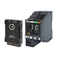
Consistently and remotely monitor and analysis the temperature status of panel devices to achieve both labor-saving and significant risk mitigation of abnormal stop
Related Contents
- Features
- Lineup
- Specifications
- Dimensions
- Catalog / Manual / CAD / Software
last update: March 18, 2024
Main Unit Specifications
Ratings
| Model | K6PM-THMD-EIP | |
|---|---|---|
| Power
supply |
Power supply voltage | 24 VDC |
| Allowable operating voltage range | 85% to 110% of the power supply voltage | |
| Power supply frequency range | --- | |
| Power consumption | 1.6 W max. | |
| Input | Compatible sensor | K6PM-THS3232 |
| Number of connected K6PM sensors | 31 units | |
| Output | Output form | Transistor output |
| Number of outputs | 3 points: | |
| Rated voltage | 24 VDC | |
| Maximum current | 50 mA | |
| Ambient operating temperature | -10 to +55 °C (with no condensation or freezing) | |
| Ambient storage temperature | -20 to +65 °C (with no condensation or freezing) | |
| Ambient operating humidity | 25% to 85% (with no condensation) | |
| Storage humidity | 25% to 85% (with no condensation) | |
| Exterior color | Black | |
| Case material | PC UL94-V0 | |
| Altitude | 2,000 m max. | |
| Applicable wires | Stranded wires, solid wires, or ferrules | |
| Applicable wire size | 0.25 to 1.5 mm2 (AWG24 to AWG16) | |
| Wire insertion force | 8 N max. for AWG20 wire | |
| Screwdriver insertion force | 15 N max. | |
| Wire stripping length | 8 mm *1, 10 mm, 12 mm | |
| Recommended Flat-blade Screwdriver | XW4Z-00B | |
| Current capacity | 10 A (per pole) | |
| Number of insertions | 50 times | |
| Weight | Approx. 200 g | |
| Mounting *2 | DIN Track mounting | |
| Screw Mounting | ||
| Dimensions | 45 (W) × 90 (H) × 90 (D) mm | |
| Setting method | Communications settings from software tool | |
| Other functions | Display value selection, Main Unit error and K6PM sensor error output, setting parameters initialization, running time | |
| Accessories | Instruction manual | |
*1. Without ferrules
*2. For details on mounting on a DIN track and screw attachment, refer to K6PM Thermal Condition Monitoring Device User's Manual (H231).
Characteristics
| Model | K6PM-THMD-EIP | ||
|---|---|---|---|
| Temperature measurement range | The temperature measurement range is described in the thermal sensor (K6PM-THS3232) performance. | ||
| Measurement temperature accuracy | The measurement temperature accuracy is described in the thermal sensor (K6PM-THS3232) performance. | ||
| Sampling cycle for the sensor | Approx. 1 second/Unit | ||
| External
trigger |
External contact
input specifications |
Short circuit: Residual voltage 1.5 V or less | |
| Open: Leakage current 0.1 mA or less | |||
| Short circuit current | Approx. 7 mA | ||
| Alarm | Measurement parameters | Current temperature, differential temperature, sensor internal temperature | |
| Expression method | Transistor output, alarm bar display | ||
| Number of variables | Two threshold values per segment (Threshold 1 and Threshold 2) | ||
| Threshold setting range | 0.0 to 999.9°C (0.0 to 999.9°F) | ||
| Hysteresis | 3.0°C width (5.4°F width) | ||
| Resetting method | Manual resetting *1 or automatic resetting (switching) | ||
| LCD display | 7-segment digital displays and individual indicators | ||
| Display resolution | 0.1°C | ||
| Applicable standards | Approved standards | UL61010-1 (Listing) installation location: Pollution level 2, South Korean Radio Law | |
| Conforming standards | RCM | ||
| EMC | EN61326-1 (EMI: Class A EMS: Industrial Location) | ||
| Recommended fuse | T2A, time lag, high shut-off capacity | ||
| Insulation resistance | 20 MΩ min.
Between all external terminals and the case Between all power supply terminals and all other terminals Between all RS-485 communications terminals, and all external trigger input terminals, all transistor output terminals and all Ethernet ports |
||
| Dielectric strength | 2,000 VAC for 1 minute
Between all external terminals and the case Between all power supply terminals and all other terminals Between all RS-485 communications terminals, and all external trigger input terminals, all transistor output terminals and all Ethernet ports |
||
| Vibration resistance | Frequency: 10 to 55 Hz, 0.35-mm single amplitude in X, Y, and Z directions (10 sweeps of 5 min each) | ||
| Shock resistance | 150 m/s2, 3 times each in X, Y, and Z axes, 6 directions | ||
| Degree of protection | IP20 | ||
| Warranty period | 1 year | ||
| Indicators | Alarm bar | Red, yellow, and green | |
| MS and NS | Red and green | ||
| Ethernet
Communi caitons |
Supported services | EtherNet/IP (tag data link or CIP message communications)
BOOTP client Modbus TCP |
|
| Physical layer | 100 Base-TX | ||
| Transmission
specifications |
Transmission speed | 100 Mbps | |
| Transmission medium | Twisted pair cable (with shield: STP): Category 5 or higher | ||
| Transmission distance | 100 m max. (distance between hub and node) | ||
| Tag data
link *2 |
Class1 | Connection resource: 4 max. | |
| Packet interval (RPI) | 1,000 to 10,000 ms | ||
| Timeout value | Multiples of RPI (4 times, 8 times, 16 times, 32 times, 64 times, 128 times, 256 times, 512 times) | ||
| Connection type | Point To Point Connection (fixed) | ||
| Explicit
message *2 |
Class 3 | Number of clients that can communicate at one time: 2 max. | |
| UCMM | Number of clients that can communicate at one time: 2 max. | ||
| Modbus
message *2 |
Modbus TCP | Number of clients that can communicate at one time: 2 max. | |
| Factory
default values |
IP address. | 192.168.250.30 | |
| Subnet mask. | 255.255.255.0 | ||
| The default gateway. | 0.0.0.0 | ||
| IP address setting method | Static IP address | ||
*1. Manual resetting method: Press and hold the SEG/ALM RST Button
*2. When you use tag data link, explicit message communications, and Modbus message communications simultaneously, limit the number of client nodes to 4 or less. If simultaneous communication is carried out with 5 or more nodes, a timeout may occur due to the communications load.
Indicator specifications
| Symbol | Name | Color | Status | Operating condition |
|---|---|---|---|---|
| MS | Module
Status |
Green | Lit. | Normal status |
| Flashes at
1-s intervals |
BOOTP server connection error state | |||
| Red | Lit. | One of the following fatal errors (Main Unit internal error)
• Internal CPU error • Internal memory error |
||
| Flashes at
1-s intervals. |
One of the following conditions
• K6PM sensor communications error • The detection of the K6PM sensor angle deviation • Sensor type error • Temperature measurement range exceeded • Running time error |
|||
| --- | Not lit. | No power supply | ||
| NS | Network
Status |
Green | Lit. | Tag data link or message connection established |
| Flashes at
1-s intervals. |
No tag data link or message connection established | |||
| Red | Lit. | IP address duplication status | ||
| Flashes at
1-s intervals. |
The connection has timed out | |||
| --- | Not lit. | No power supply, or IP address not set |
Transistor output specifications
| Name | Description | |
|---|---|---|
| Transistor
Output 1 |
Threshold 1 excess output of comprehensive alarm. | If threshold 1 exceeded occurs for the
comprehensive alarm, transistor output 1 remains OFF and transistor output 2 remains ON. If threshold 2 exceeded occurs for the comprehensive alarm, both transistor output 1 and transistor output 2 turn OFF. (Normally closed type) |
| Transistor output type can be set to Normally Closed
or Normally Open. |
||
| Transistor
Output 2 |
Threshold 2 excess output of comprehensive alarm.
Transistor output type can be set to Normally Closed or Normally Open. |
|
| Transistor
Output 3 *3 |
• This is the output of the Main Unit or K6PM-TH sensor error *1, or the output that determines whether the
Main Unit is in setting mode or monitoring mode. • The output type of transistor output 3 is fixed as Normally closed. • Depends on the setting of the TR3 output mode parameter. *2 Set the TR3 output mode to 0: Error existence Transistor output 3 is turned ON: No error occurred in the Main Unit or K6PM-TH sensor Transistor output 3 is turned OFF: Error occurred in the Main Unit or K6PM-TH sensor Set the TR3 output mode to 0: Monitoring existence Transistor output 3 is turned ON: In monitoring mode, and no error occurred in the Main Unit or K6PM-TH sensor. Transistor output 3 is turned OFF: In setting mode, and an error occurred in the Main Unit or K6PM-TH sensor. |
|
*1. The Main Unit error and K6PM-TH sensor error specify any one of the following:
• Main Unit internal error (internal CPU error or internal memory error)
• K6PM-TH sensor communications error or sensor type error
• The detection of the K6PM-TH sensor angle deviation
• Temperature measurement range exceeded
• Running time error
*2. TR3 output mode parameter can be operated with K6PM-TH Main Unit EIP Ver. 1.1 or later and Condition Monitoring Configuration Tool Ver. 1.2 or higher.
*3. The operation of transistor output 3 is as described below.
| Transistor output 3 | Condition | ||
|---|---|---|---|
| TR3 output
mode 0: Error existence (default) |
TR3 output
mode 1: Monitored existence |
K6PM-TH Main Unit | Infrared Thermal Sensor |
| OFF | OFF | Operating | |
| Main Unit internal error | |||
| ON | OFF | In setting mode
(K6PM-TH sensor search mode or K6PM-TH sensor position adjustment mode) |
Before data acquisition |
| Normal | |||
| OFF | OFF | K6PM-TH sensor communications error or sensor type error | |
| The detection of the K6PM-TH sensor angle deviation | |||
| Temperature measurement range exceeded | |||
| Running time error | |||
| ON | ON | In monitoring mode | Before data acquisition |
| Normal | |||
| OFF | OFF | K6PM-TH sensor communications error or sensor type error | |
| The detection of the K6PM-TH sensor angle deviation | |||
| Temperature measurement range exceeded | |||
| Running time error | |||
Measured value display
| Measurement level | Methods for checking | ||
|---|---|---|---|
| Main Unit (display) | Software tool | Communicaitons | |
| Temperature of each segment and sensor internal temperature | The segment display of each sensor can be switched on the Main Unit front-panel. | Can be checked on the Alarm setting screen. | • EtherNet/IP tag data link communications
• EtherNet/IP message communications • Modbus TCP communications |
| Differential temperature per segment from the K6PM-TH sensor internal temperature | Not supported | Not supported | Not supported |
| Temperature of each infrared thermal sensor | Not supported | The past maximum value can be monitored on the Alarm setting screen. | Not supported |
| Temperature of each pixel | Not supported | The temperature can be displayed when the cursor is placed on the thermal image on the Infrared thermal sensor screen. | • EtherNet/IP message communications
• Modbus TCP communications |
| Alarms of each Main Unit
(Alarms of all infrared thermal sensors connected to the Main Unit) |
The occurrence of an alarm can be checked on the alarm bar. | The occurrence of an alarm can be checked on the Device List of logging screen. | The occurrence of an alarm can be checked from the Main Unit status. |
Infrared thermal sensor
Ratings
| Model | K6PM-THS3232 | |
|---|---|---|
| Power
supply |
Power supply voltage | 24 VDC |
| Allowable operating voltage range | 85% to 110% of the power supply voltage | |
| Power supply frequency range | --- | |
| Power consumption | 0.4 W max./Unit at 24 VDC *1 | |
| Ambient operating temperature | -10 to +55 °C (with no condensation or freezing) | |
| Storage temperature | -20 to +65 °C (with no condensation or freezing) | |
| Ambient operating humidity | 25% to 85% (with no condensation) | |
| Storage humidity | 25% to 85% (with no condensation) | |
| Exterior color | Black | |
| Case material | PC UL94-V0 | |
| Altitude | 2,000 m max. | |
| Applicable wires | Stranded wires or solid wires | |
| Applicable wire size | 0.25 to 1.5 mm2 (AWG24 to AWG16) | |
| Current capacity | 8 A (per pole) | |
| Weight | 50 g max. | |
| Mounting | Mounting *2
Screw Mounting |
|
| Dimensions | 43 × 60 × 25.1 mm (W×H×D) Terminals not included | |
| Accessories *3 | Instruction manual, mounting bracket, magnet (for positioning) *4 | |
*1. The power consumption increases according to the number of connected devices. Take note of the choice of wiring and the wiring diameter.
*2. A 1/4-20 UNC mounting hole is available (nuts are not provided).
*3. The pan head is sold separately.
*4. Use magnet mounting for positioning the sensor.
Performance
| Model | K6PM-THS3232 | |
|---|---|---|
| Temperature
measurement |
Temperature measurement
range |
Temperature measurement range: 0.0°C to 200.0°C (32.0°F to 392.0°F) |
| Detection resolution | 32 × 32 (1,024 pixels) | |
| Temperature accuracy | ±5°C (at an ambient temperature of 25°C) *1*2 | |
| Emissivity | 0.94 | |
| Reproducibility | 1°C (at an ambient temperature of 25°C) *2 | |
| Temperature drift | 0.15°C | |
| Viewing angle [FOV] | 90° × 90° | |
| Warmup time | 15 minutes | |
| Other
functions |
Over temperature
measurement range |
Temperature: 200.0°C or higher, sensor internal temperature: 80°C or higher |
| Angle deviation detection
*3 |
Angle deviations of 5° (typ) min. and those that continue for 3 seconds min. can be detected. | |
| Output | Communications method | RS-485 communications |
| Maximum cable length | 500 m | |
| Applicable
standards |
Approved standards | UL61010-1 (listing) installation location: Pollution degree 2 |
| Korean Radio Waves Act | ||
| Conforming standards | RCM | |
| EMC | EN61326-1 (EMI: Class A EMS: Industrial Location)
Measured temperature fluctuation range: ±6°C |
|
| Recommended fuse | T2A, time lag, high shut-off capacity | |
| Insulation resistance | 20 MΩ min.
Between all terminals and the case |
|
| Dielectric strength | 1,000 VAC for 1 minute
Between all terminals and the case |
|
| Vibration resistance | Frequency: 10 to 55 Hz, 0.35-mm single amplitude in X, Y, and Z directions
(10 sweeps of 5 min each) *4 |
|
| Shock resistance | 150 m/s2, 3 times each in 6 directions along 3 axes *4 | |
| Degree of protection | IP20 | |
| Indicators | Power indicator | Green (when power is on: lit, when power is not on: off) |
| Communications indicator | Orange (when communications are performed: Lit, when communications are not performed: Not lit) | |
| Alarm indicator | Red (when a sensor error occurs: Lit, when an angle deviation is detected: Flashing) | |
*1. Accuracy may vary depending on the measured distance, the object's emissivity, and ambient temperature.
*2. For details on temperature accuracy and reproducibility, refer to K6PM Thermal Condition Monitoring Device User's Manual (H231).
*3. Make ON/OFF settings on the DIP switch Pin 2 (default value: OFF).
Since the operation is not stable at a location subject to vibrations, it may not be possible to detect angle deviation.
*4. During screw mounting
Condition Monitoring Configuration Tool
Starting in February 2024, OMRON releases a software tool for configuring all models of condition monitoring devices. The unified configuration and verification environment of the software tool makes it easy to introduce condition monitoring devices. While the existing tools for condition monitoring devices will remain functional, be advised that OMRON has no plans to provide support for updates or related services. Going forward, use the Condition Monitoring Configuration Tool instead of the existing tools.
| Product name | Model | Software Tool | The last day to
download the tools |
|---|---|---|---|
| Motor Condition
Monitoring Device |
K6CM | Motor Condition Monitoring Tool *1 | 30 November, 2024 |
| Thermal Condition
Monitoring Device |
K6PM-TH | K6PM-TH Software Tool | 30 June, 2024 |
| Insulation Resistance
Monitoring Device |
K7GE-MG | K7GE-MG Logging Tool | |
| Heater Condition
Monitoring Device |
K7TM | K7TM Configuration Tool | |
| Advanced Motor Condition
Monitoring Device |
K7DD | K7DD Support Tool |
*1. The CD-ROM for the Motor Condition Monitoring Tool will no longer be supplied with K6CM manufactured in December 2024 or later.
*2. It supports only the following models in the K6CM series.
• K6CM-CI2
• K6CM-VB (EIP CPU version 1.20 or later)
• K6CM-IS (EIP CPU version 1.20 or later)

| The new Tool will be available from February 2024 onwards |
|---|
| Condition Monitoring Configuration Tool *2 |
Operating Environment
| Supported OS | Windows 10 (Version1607 or higher) and 11 (Japanese or English)
64 bit |
|---|---|
| PC specifications | CPU: 1 GHz or higher, 64 bit processor
Memory: 2 GB or higher Disk reserved area capacity: 20 GB or more Monitor resolution: 1920 × 1080 Others: LAN port (for network connection) |
How to obtain the Condition Monitoring Configuration Tool
Only download is available.
https://www.ia.omron.com/cmc_tool
last update: March 18, 2024