Discontinued On Mar. 2024
S8TS
Switch Mode Power Supply
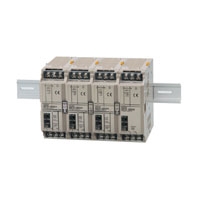
Block-type Switch Mode Power Supply That Mounts to DIN Rail
* Information in this page is a reference that you created on the basis of information in the product catalog before the end of production, may be different from the current situation, such as goods for / supported standards options / price / features of the product. Before using, please check the compatibility and safety system.
Related Contents
- Features
- Lineup
- Specifications
- Dimensions
- Catalog / Manual / CAD / Software
last update: October 1, 2020
12/24-V Models (Basic Block: S8TS-06024[]/S8TS-03012[])
| Item | Single operation | Parallel operation | ||
|---|---|---|---|---|
| Efficiency (TYP.) | 24-V models: 80% TYP. ; 12-V models: 73% TYP. (with rated input, 100% load) | |||
| Input | Voltage *1 | Ratings: 100 to 240 VAC (Allowable range: 85 to 264 VAC, 80 to 370 VDC *8) | ||
| Frequency *1 | 50/60 Hz (47 to 63 Hz) | |||
| Current | 100 V input | 24-V models: 1.0 A max.
12-V models: 0.7 A max. |
24-V models: 1.0 A × (No. of Blocks) max.
12-V models: 0.7 A × (No. of Blocks) max. |
|
| 200 V input | 24-V models: 0.5 A max.
12-V models: 0.4 A max. |
24-V models: 0.5 A × (No. of Blocks) max.
12-V models: 0.4 A × (No. of Blocks) max. |
||
| Power factor | 24-V models: 0.9 min.; 12-V models: 0.8 min. (with rated input, 100% load) | |||
| Harmonic current
emissions |
Conforms to EN61000-3-2 | |||
| Leakage
current |
100 V input | 0.35 mA max. | 0.35 mA × (No. of Blocks) max. | |
| 240 V input | 0.7 mA max. | 0.7 mA × (No. of Blocks) max. | ||
| Inrush
current *5 |
100 V input | 17.5 A max. (for a cold start at 25°C) | 17.5 A × (No. of Blocks) max. (for a cold
start at 25°C) |
|
| 200 V input | 35 A max. (for a cold start at 25°C) | 35 A × (No. of Blocks) max. (for a cold
start at 25°C) |
||
| Output
*4 |
Voltage adjustment
range |
24-V models: 22 to 28 V
12-V models: 12 V ±10% (with V.ADJ) *2 |
||
| Ripple | 2% (p-p) max. | |||
| Input variation
influence |
0.5% max. (with 85 to 264 VAC input, 100% load) | |||
| Load variation
influence |
2% max. (with rated input, 10% to
100% load) |
3% max. (with rated input, 10% to 100% load) | ||
| Temperature variation
influence |
0.05%/°C max. (with rated input and output) | |||
| Startup time | 1,000 ms max. (with 100/200 VAC, rated input) | |||
| Hold time *5 | 20 ms min. (with 100/200 VAC, rated input) | |||
| Addi-
tional func- tions |
Overload protection
*5 |
105% to 140% of rated load current,
voltage drop, automatic reset |
100% to 140% of rated load current, voltage
drop, automatic reset |
|
| Overvoltage
protection *5 *6 |
Yes | |||
| Parallel operation | Yes (Up to 4 Blocks) | |||
| N+1 redundant
system |
Yes (Up to 5 Blocks) | |||
| Series operation | Yes | |||
| Undervoltage
indicator *5 |
Yes (color: red) | |||
| Undervoltage
detection output *5 |
Yes (open collector output), 30 VDC max., 50 mA max. | |||
| Other | Ambient operating
temperature *5 |
Refer to the derating curve in Engineering Data on Data Sheet (with no icing or
condensation). |
||
| Storage temperature | -25 to 65°C | |||
| Ambient operating
humidity |
25% to 85% (Storage humidity: 25% to 90%) | |||
| Dielectric strength | 3.0 kVAC for 1 minute (between all inputs and all outputs; detection current: 20 mA) | |||
| 2.0 kVAC for 1 minute (between all inputs and PE terminal; detection current: 20 mA) | ||||
| 1.0 kVAC for 1 minute (between all outputs and PE terminal; detection current: 20
mA) |
||||
| Insulation resistance | 100 MΩ min. (between all outputs, and all inputs/PE terminal) at 500 VDC | |||
| Vibration resistance
*7 |
10 to 55 Hz, 0.375-mm single amplitude for 2 h each in X, Y, and Z directions | |||
| Shock resistance *7 | 150 m/s2, 3 times each in ±X, ±Y, and ±Z directions | |||
| Output indicator | Yes (color: green) | |||
| EMI *8 | Conducted
Emission |
Conforms to EN61204-3 EN55011 Class B and based on FCC Class A *9 | ||
| Radiated
Emission |
Conforms to EN61204-3 EN55011 Class B *9 | |||
| EMS *8 | Conforms to EN61204-3 High severity levels *9 | |||
| Approved standards
*8 |
24V model
UL Listed: UL508 (Listing, Class2 Output: Per UL1310) (See note 3.) cUL Listed: CSA C22.2 No.107.1 (Class2 Output: Per CSA C22.2 No.223) (See note 3.) EN: EN62477-1 12V model UL Listed: UL508 (Listing) cUL Listed: CSA C22.2 No.107.1 EN: EN62477-1 |
|||
| Weight | 450 g max. | 450 g × (No. of Blocks) max. | ||
*1. Do not use an inverter output for the Power Supply. Inverters with an output frequency of 50/60 Hz are available, but
the rise in the internal temperature of the Power Supply may result in ignition or burning.
*2. Refer to Data sheet for details on adjusting the output voltage for parallel operation. If set to less than −10%, the
undervoltage detection function may operate. Ensure that the output capacity and output current after adjustment do
not exceed the rated output capacity and rated output current respectively. Adjusting V.ADV may cause the output
voltage to exceed the voltage range. When adjusting the output voltage, confirm the actual output voltage from the
Power Supply and be sure that the load is not damaged.
*3. Class 2 approval does not apply to parallel operation.
*4. The output current is specified at power output terminals.
*5. Refer to the Engineering Data on Data sheet for details.
*6. To reset the protection, turn OFF the input power for one minute or longer and then turn it back again.
*7. Be sure to mount End Plates (PFP-M) on both ends of the Power Supply.
*8. The range for compliance with EC Directives and safety standards (UL, EN, etc.) is 100 to 240 VAC (85 to 264 VAC).
*9. The noise level depends on the wiring method and other factors. Insert one clamp filter (the ZCAT2436-1330A from
TDK) as a noise countermeasure on the input line and ground line combined.
5-V Models (Basic Block: S8TS-02505[])
| Item | Single operation | ||
|---|---|---|---|
| Efficiency (typical) | 73% TYP. (with rated input, 100% load) | ||
| Input | Voltage *1 | Ratings: 100 to 240 VAC (Allowable range: 85 to 264 VAC, 80 to 370 VDC *7) | |
| Frequency *1 | 50/60 Hz (47 to 63 Hz) | ||
| Current | 100 V input | 0.7 A max. | |
| 200 V input | 0.4 A max. | ||
| Power factor | 0.8 min. (with rated input, 100% load) | ||
| Harmonic current emissions | Conforms to EN61000-3-2 | ||
| Leakage
current |
100 V input | 0.35 mA max. | |
| 240 V input | 0.7 mA max. | ||
| Inrush
current *5 |
100 V input | 17.5 A max. (for a cold start at 25°C) | |
| 200 V input | 35 A max. (for a cold start at 25°C) | ||
| Output
*3 |
Voltage adjustment range | 5 V ± 10% (with V. ADJ) *2 | |
| Ripple | 2% (p-p) max. | ||
| Input variation influence | 0.5% max. (with 85 to 264 VAC input, 100% load) | ||
| Temperature variation
influence |
0.05%/°C max. (with rated input and output) | ||
| Load variation influence | 1.5% max. (with rated input, 10% to 100% load) | ||
| Startup time *4 | 1,000 ms max. (with 100/200 VAC, rated input) | ||
| Hold time *4 | 20 ms min. (with 100/200 VAC, rated input) | ||
| Addi-
tional func- tions |
Overload protection *4 | 105% to 140% of rated load current, voltage drop, automatic reset | |
| Overvoltage protection
*4 *5 |
Yes | ||
| Parallel operation | No | ||
| N+1 redundant system | No | ||
| Series operation | Yes (with the external diode) | ||
| Undervoltage indicator *4 | Yes (color: red) | ||
| Undervoltage detection
output *4 |
Yes (open collector output), 30 VDC max., 50 mA max. | ||
| Other | Ambient operating
temperature *4 |
Refer to the derating curve in Engineering Data on Data Sheet. | |
| Storage temperature | -25 to 65°C (with no icing or condensation) | ||
| Ambient operating humidity | 25% to 85%, Storage: 25% to 90% | ||
| Dielectric strength | 3.0 kVAC, 50/60 Hz for 1 minute (between all inputs and all outputs; detection
current: 20 mA) |
||
| 2.0 kVAC, 50/60 Hz for 1 minute (between all inputs and PE terminal; detection
current: 20 mA) |
|||
| 1.0 kVAC for 1 minute (between all outputs and PE terminal; detection current:
20 mA) |
|||
| Insulation resistance | 100 MΩ min. (between all outputs and inputs/PE terminal) at 500 VDC | ||
| Vibration resistance *6 | 10 to 55 Hz, 0.375-mm single amplitude for 2 h each in X, Y, and Z directions | ||
| Shock resistance *6 | 150 m/s2, 3 times each in ±X, ±Y, and ±Z directions | ||
| Output indicator | Yes (color: green) | ||
| EMI *7 | Conducted
Emission |
Conforms to EN61204-3 EN55011 Class B and based on FCC Class A | |
| Radiated
Emission |
Conforms to EN61204-3 EN55011 Class B | ||
| EMS *7 | Conforms to EN61204-3 High severity levels | ||
| Approved standards *7 | UL Listed: UL508 (Listing)
UL UR: UL60950-1 (Recognition) cUL Listed: CSA C22.2 No.107.1 cUR: CSA C22.2 No.60950-1 EN/VDE: EN50178 (=VDE0160), EN60950-1 (=VDE0805 Teil1) |
||
| Weight | 450 g max. | ||
*1. Do not use an inverter output for the Power Supply. Inverters with an output frequency of 50/60 Hz are available, but
the rise in the internal temperature of the Power Supply may result in ignition or burning.
*2. If set to less than −10%, the undervoltage detection function may operate. Ensure that the output capacity and output
current after adjustment do not exceed the rated output capacity and rated output current respectively. If the output
voltage adjuster (V. ADJ) is turned, the voltage will increase by more than 10% of the output voltage, confirm the actual
output voltage from the Power Supply and be sure that the load is not damaged.
*3. The output current is specified at power output terminals.
*4. Refer to the Engineering Data on Data sheet for details.
*5. To reset the protection, turn OFF the input power for one minute or longer and then turn it back again.
*6. Be sure to mount End Plates (PFP-M) on both ends of the Power Supply.
*7. The range for compliance with EC Directives and safety standards (UL, EN, etc.) is 100 to 240 VAC (85 to 264 VAC).
last update: October 1, 2020
 Product Category
- Power Supplies / In Addition
-
Power Supplies
-
Discontinued
- S8TS
-
Discontinued
-