KM50-E
Smart Power Monitor
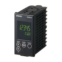
Power and current can be measured simultaneously. Measurement of generated power (regenerative power), leading reactive power, lagging reactive power, and consumed power. High-performance Power Monitor.
Related Contents
last update: January 5, 2026
(Unit: mm)
Smart Power Monitor
KM50-E1-FLK
Panel Mounting Dimensions
- Use M3.5 crimp terminals.
- The mounting panel must be 1 to 8 mm thick.
- When mounting KM50-E Power Monitors side by side, provide sufficient space between them.
Reference separation: 120 mm (vertical), 60 mm (horizontal)
Both of these are distances from the center of the Power Monitor. - Make sure that the rated ambient temperature of the KM50-E Power Monitor is not exceeded when more than one Power Monitor is mounted.
CT
KM20-CTF-5A
KM20-CTF-50A
KM20-CTF-100A
KM20-CTF-200A
KM20-CTF-400A/600A
KM20-CTF-CB3 (Special CT Cable)
Special CTs and CT Cable
- Use only the CTs and CT Cable specified by OMRON.
- If any other CTs or CT Cables are used, normal measurements will not be possible.
- The Special CTs have polarity.
Connect the Special CT correctly, connecting the 1S or 3S terminal on the Power Monitor to the k terminal on the CT and the 1L or 3L terminal on the Power Monitor to the l terminal on the CT. - Do not ground the Special CTs. Failure may occur.
Special CTs for the KM20-B40 and KM20-B40-FLK
Rated primary current of 5 A: KM20-CTF-5A
Rated primary current of 50 A: KM20-CTF-50A
Rated primary current of 100 A: KM20-CTF-100A
Rated primary current of 200 A: KM20-CTF-200A
Rated primary current of 400 A: KM20-CTF-400A
Rated primary current of 600 A: KM20-CTF-600A
KM20-CTF-series CT Cable
KM20-CTF-CB3 (3 m)
Optional Accessories
Mounting Bracket
KM50-OPT-ED1
KM50-OPT-EM1
last update: January 5, 2026