Discontinued On Mar. 2025
E5CSV
Temperature Controllers
Easy Setting Using DIP Switch and Simple Functions in DIN 48 × 48 mm-size Temperature Controllers
* Information in this page is a reference that you created on the basis of information in the product catalog before the end of production, may be different from the current situation, such as goods for / supported standards options / price / features of the product. Before using, please check the compatibility and safety system.
Related Contents
- Features
- Lineup
- Specifications
- Dimensions
- Catalog / Manual / CAD / Software
last update: August 5, 2015
Ratings
| Supply voltage | 100 to 240 VAC, 50/60 Hz
24 VAC, 50/60 Hz; 24 VDC |
|
|---|---|---|
| Operating voltage range | 85% to 110% of rated supply voltage | |
| Power consumption | 100 to 240 VAC: 5 VA
24 VAC: 3 VA, 24 VDC: 2 W |
|
| Sensor input | Thermocouple input type: K, J, L
Platinum resistance thermometer input type: Pt100, JPt100 Universal-input (thermocouple/platinum resistance thermometer) type: K, J, L, T, U, N, R, Pt100, JPt100 |
|
| Control
output |
Relay output | SPST-NO, 250 VAC, 3A (resistive load) |
| Voltage output
(for driving the SSR) |
12 VDC, 21 mA (with short-circuit protection circuit) | |
| Control method | ON/OFF or 2-PID (with auto-tuning) | |
| Alarm output | SPST-NO, 250 VAC, 1A (resistive load) | |
| Setting method | Digital setting using front panel keys | |
| Indication method | 7-segment digital display (character height: 13.5 mm) and deviation indicators | |
| Other functions | Setting change prohibit (key protection)
Input shift Temperature unit change (°C/°F) Direct/reverse operation Temperature range, Sensor switching (K/J/L, Pt100/JPt100) Switching is performed between a thermocouple and platinum resistance thermometer for universal-input models. Control period switching 8-mode alarm output Sensor error detection |
|
| Ambient operating
temperature |
-10 to 55°C (with no condensation or icing); with 3-year guarantee: -10 to 50°C | |
| Ambient operating humidity | 25% to 85% | |
| Storage temperature | -25 to 65°C (with no condensation or icing) | |
2. Models for 24 VAC/DC can also be manufactured.
Characteristics
| Setting accuracy | Thermocouple (See note 1.): (±0.5% of indication value or ±1°C, whichever is greater) ±1 digit max.
Platinum resistance thermometer (See note 2.): (±0.5% of indication value or ±1°C, whichever is greater) ±1 digit max. |
|
|---|---|---|
| Indication accuracy
(ambient temperature of 23°C) |
||
| Influence of temperature | R thermocouple inputs: (±1% of PV or ±10°C, whichever is greater) ±1 digit max.
Other thermocouple inputs: (±1% of PV or ±4°C, whichever is greater) ±1 digit max. Platinum resistance thermometer inputs: (±1% of PV or ±2°C, whichever is greater) ±1 digit max. |
|
| Influence of voltage | ||
| Influence of EMS.
(at EN61326-1) |
||
| Hysteresis
(for ON/OFF control) |
0.2% FS (0.1% FS for universal-input (thermocouple/platinum resistance thermometer) models) | |
| Proportional band (P) | 1 to 999°C (automatic adjustment using auto-tuning/self-tuning) | |
| Integral time (I) | 1 to 1,999 s (automatic adjustment using auto-tuning/self-tuning | |
| Derivative time (D) | 1 to 1,999 s (automatic adjustment using auto-tuning/self-tuning) | |
| Alarm output range | Absolute-value alarm: Same as the control range
Other: 0 to input setting range full scale (°C or °F) Alarm hysteresis: 0.2°C or °F (fixed) |
|
| Control period | 2/20 s | |
| Sampling period | 500 ms | |
| Insulation resistance | 20 MΩ min. (at 500 VDC) | |
| Dielectric strength | 2,000 VAC, 50/60 Hz for 1 min between current-carrying terminals of different polarity | |
| Vibration
resistance |
Malfunction | 10 to 55 Hz, 20 m/s2 for 10 min each in X, Y, and Z directions |
| Destruction | 10 to 55 Hz, 0.75-mm single amplitude for 2 hr each in X, Y, and Z directions | |
| Shock
resistance |
Malfunction | 100 m/s2 min., 3 times each in 6 directions |
| Destruction | 300 m/s2 min., 3 times each in 6 directions | |
| Life
expectancy |
Electrical | 100,000 operations min. (relay output models) |
| Weight | Approx. 120 g (Controller only) | |
| Degree of protection | Front panel: Equivalent to IP66; Rear case: IP20; Terminals: IP00 | |
| Memory protection | EEPROM (non-volatile memory) (number of writes: 1,000,000) | |
| EMC | EMI Radiated: EN 55011 Group 1 Class A
EMI Conducted: EN 55011 Group 1 Class A ESD Immunity: EN 61000-4-2: 4 kV contact discharge (level 2), 8 kV air discharge (level 3) Radiated Electromagnetic Field Immunity: EN 61000-4-3: 10 V/m (80-1000 MHz, 1.4-2.0 GHz amplitude modulated) (level 3), 10 V/m (900 MHz pulse modulated) Conducted Disturbance Immunity: EN 61000-4-6: 3 V (0.15 to 80 MHz) (level 2) Noise Immunity (First Transient Burst Noise): EN 61000-4-4 Burst Immunity: 2 kV power-line (level 3), 1 kV I/O signal-line (level 3) Surge Immunity: EN 61000-4-5: Power line: Normal mode 1 kV; Common mode 2 kV, Output line (relay output): Normal mode 1 kV; Common mode 2 kV Voltage Dip/Interrupting Immunity: EN 61000-4-11 0.5 cycle, 100% (rated voltage) |
|
| Approved standards | UL 61010-1 (listing)
CSA C22.2 No.1010-1 |
|
| Conformed standards | EN61326-1 (See note 3.), EN61010-1, IEC61010-1
VDE 0106 Part 100 (finger protection), when the terminal cover is mounted. |
|
Note: 1. The following exceptions apply to thermocouples.
• U, L: ±2°C ±1 digit max.
• R: ±3°C ±1 digit max. at 200°C or less
2. The following exceptions apply to platinum resistance thermometers.
Input set values 0, 1, 2, 3 for E5CSV: 0.5% FS ±1 digit max.
3. Industrial electromagnetic environment (EN/IEC 61326-1 Table 2)
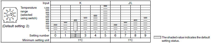
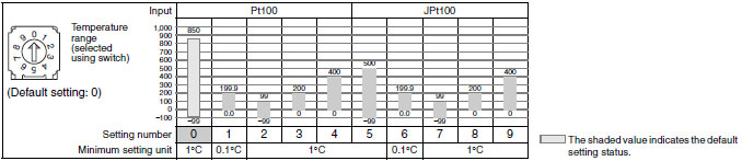
Temperature Range
Thermocouple Input Models
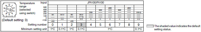
Platinum Resistance Thermometer Input Models
Universal-input (Thermocouple/Platinum Resistance Thermometer) Models
Using Thermocouple Sensors, Control Mode Switch 5: OFF
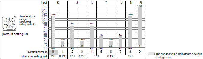
Using Platinum Resistance Thermometers, Control Mode Switch 5: ON
last update: August 5, 2015
 Product Category
- Control Components
-
Temperature Controllers
-
Discontinued
- E5CSV
-
Discontinued
-